Coordinate detecting method and system for touch panel

a technology of coordinate detection and touch panel, which is applied in transmission systems, instruments, and cathode-ray tube indicators, etc., can solve the problems of nonlinear voltage gradient in practice, the number of x-axis and y-axis scanning wires cannot be increased, and the resolution of the touch panel used in the method cannot be improved, so as to improve the resolution of the touch panel and reduce the number of i/o ports

Inactive Publication Date: 2007-01-30
HONOUR INT
View PDF8 Cites 14 Cited by
  • Summary
  • Abstract
  • Description
  • Claims
  • Application Information

AI Technical Summary

Benefits of technology

[0013]According to the coordinate detecting method of the invention, the X-axis and Y-axis I / O ports are converted to X-axis and Y-axis scanning wires respectively by orthogonal method. The number of the I / O ports can be reduced, and the resolution of the touch panel can be improved. For the calculation method, the invention utilizes simple comparing method to obtain the largest detection signal and the second largest detection signal so as to calculate the coordinate position of the pen touching the touch panel. Therefore, the coordinate detecting method of the invention is very simple and rapid.

Problems solved by technology

Because the method utilizes the I / O ports of the controller and the number of the I / O ports is limited, the number of the X-axis and Y-axis scanning wires cannot be increased and the resolution of the touch panel used in the method cannot be improved.
Although the voltage gradient is linear in theory, the voltage gradient is nonlinear in practice.
Therefore, the method for calculating the coordinate position is complex.
However, to overcome the unstable characteristic of the resistance material and the difference in electrical field intensity between the branched nodes, the calculation method is very complex to obtain the coordinate position of the pen.
The complexity of software for the divided voltage type coordinate detecting method is higher than that of the non-touching electrical field type coordinate detecting method.
The fewer I / O ports the controller has, the more complex the calculation method is.

Method used


Image

  • Coordinate detecting method and system for touch panel
  • Coordinate detecting method and system for touch panel
  • Coordinate detecting method and system for touch panel

Examples


Embodiment Construction

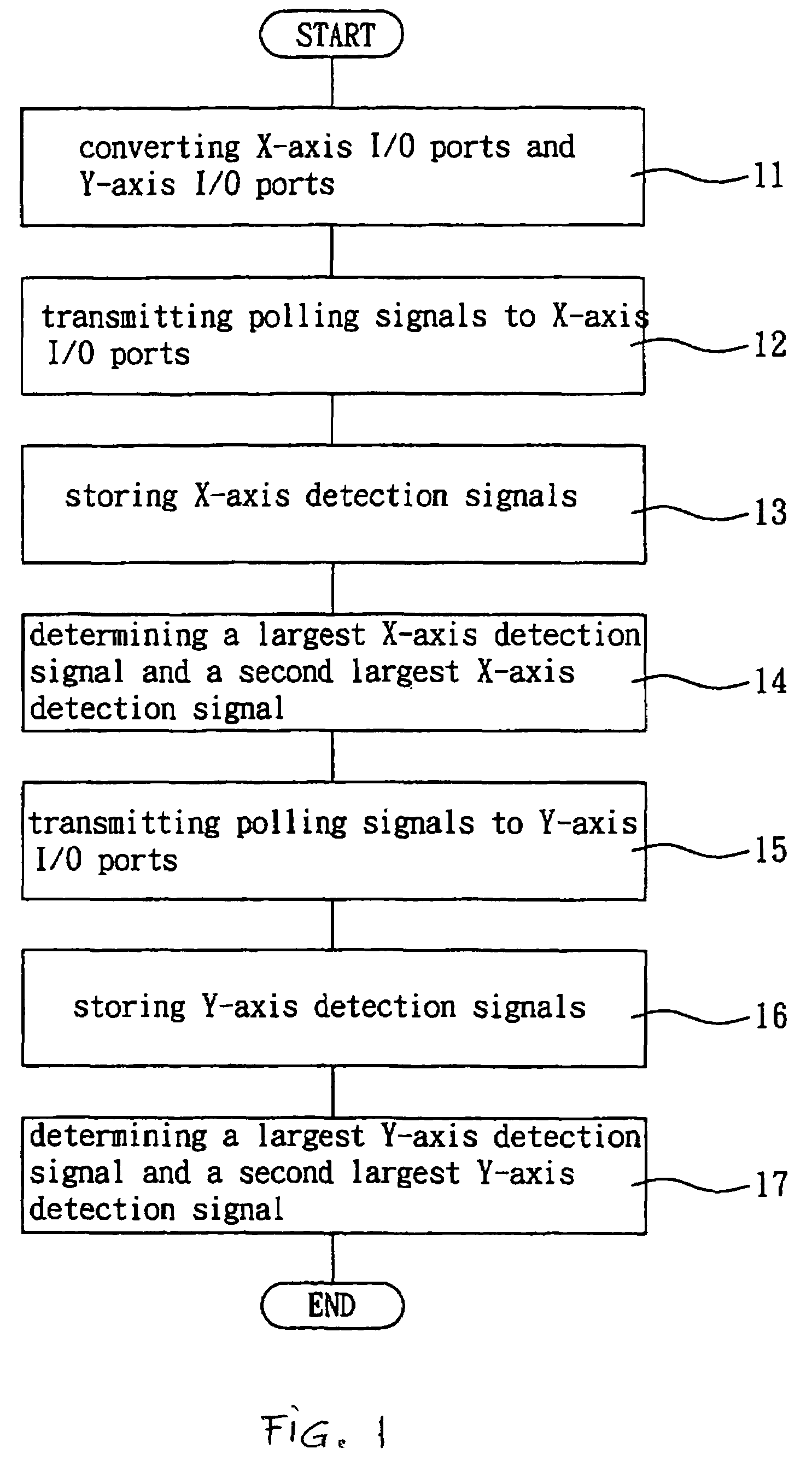
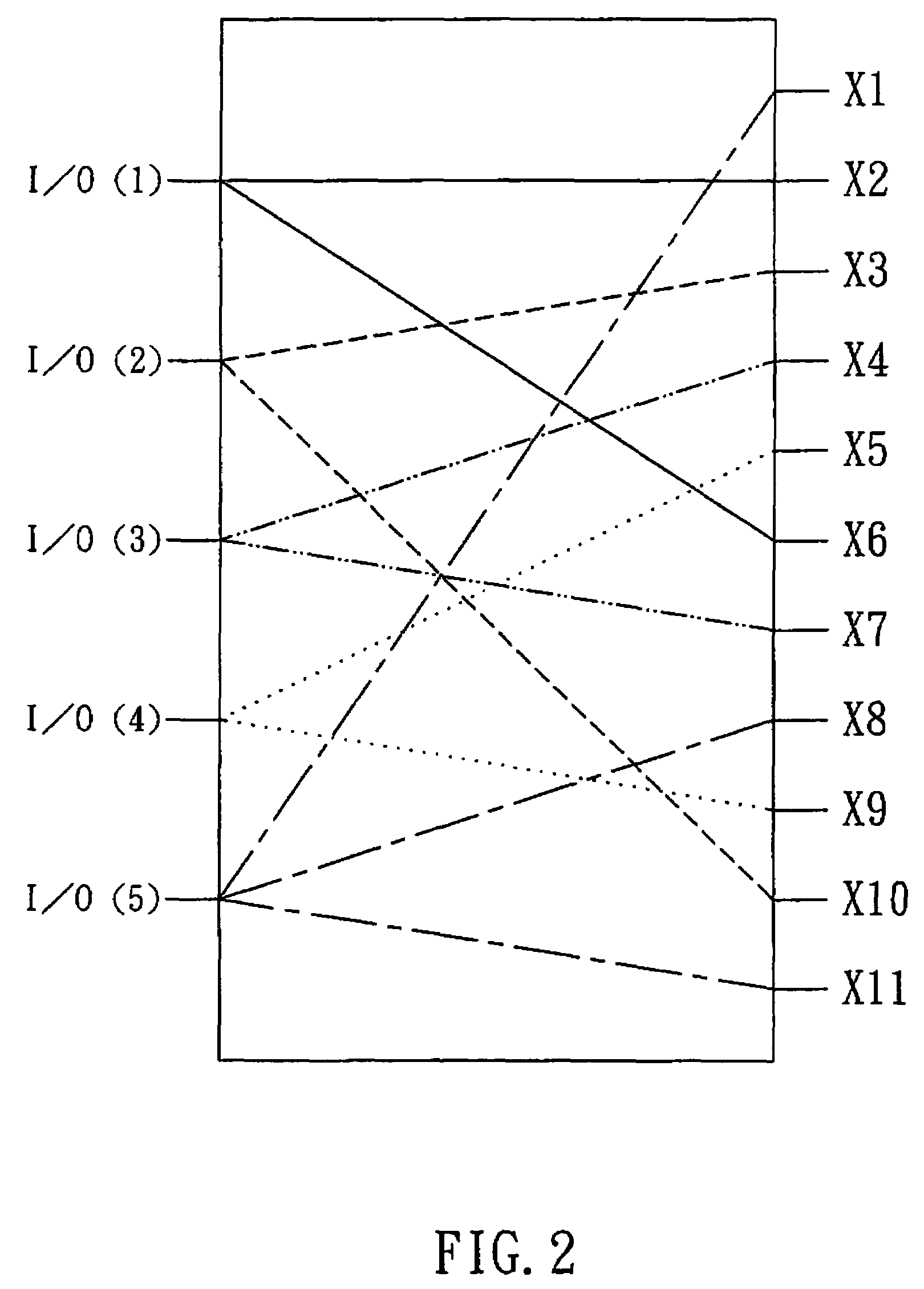
[0020]Referring to FIG. 1, in step 11, a plurality of X-axis I / O ports and a plurality of Y-axis I / O ports are converted respectively to form a plurality of X-axis scanning wires and a plurality of Y-axis canning wires of the touch panel by orthogonal method. Referring to FIG. 2, five X-axis I / O ports I / O(1), I / O(2), I / O(3), I / O(4) and I / O(5) are converted to eleven X-axis scanning wires (X1 to X11). I / O(1) is connected to X2 and X6 scanning wires. I / O(2) is connected to X3 and X10 scanning wires. I / O(3) is connected to X4 and X7 scanning wires. I / O(4) is connected to X5 and X9 scanning wires. I / O(5) is connected to X1, X8 and X11 scanning wires.

[0021]In the above converted method, the number of the I / O ports is lower than that of the scanning wires, and the arrangement of the scanning wires must obey the orthogonal method. That is, a scanning interval between two scanning wires is correlative to the unique I / O ports. For example, a scanning interval between X1 and X2 scanning wires...


PUM


Abstract

The invention relates to a coordinate detecting method for a touch panel. Firstly, a plurality of X-axis and Y-axis I / O ports are converted to a plurality of X-axis and Y-axis scanning wires respectively by orthogonal method. Polling signals are transmitted to X-axis I / O ports, and are transmitted to the X-axis scanning wires. According to the polling signals, a plurality of X-axis detection signals are stored. A largest X-axis detection signal and a second largest X-axis detection signal are determined by compared method so as to calculate a X coordinate position of the sensor pen touching the touch panel. The steps are repeated to calculate the Y coordinate position of the sensor pen touching on the touch panel. According to the coordinate detecting method of the invention, the number of the I / O ports can be reduced, and the resolution of the touch panel can be improved. For the calculation method, the invention utilizes simple compared method to obtain the largest detection signal and the second largest detection signal so as to calculate the coordinate position of the sensor pen touching on the touch panel. Therefore, the coordinate detecting method of the invention is very simple and rapid.

Description

BACKGROUND OF THE INVENTION[0001]1. Field of the Invention[0002]The present invention relates to a coordinate detecting method and system, more particularly, to a coordinate detecting method and system for a touch panel.[0003]2. Description of the Related Art[0004]The conventional coordinate detecting methods for the touch panels include a touching matrix coordinate detecting method, a non-touching electrical field type or capacitive type coordinate detecting method and divided voltage type coordinate detecting method.[0005]The touching matrix coordinate detecting method utilizes a controller having a plurality of I / O ports to form a plurality of X-axis and Y-axis scanning wires. The controller sends signals to the X-axis scanning wires, and reads signals from the Y-axis scanning wires so that a coordinate position touched by the user can be obtained. Because the method utilizes the I / O ports of the controller and the number of the I / O ports is limited, the number of the X-axis and ...

Claims


Application Information

Patent Timeline
Patent Type & Authority Patents(United States)
IPC IPC(8): G09G5/00G06K11/06G06F3/041G06F3/03G06F3/033G06F3/044G06F3/045G06F3/046G06F3/047G09G3/34
CPCG06F3/03545G06F3/041G06F3/047G06F3/045G06F3/046G06F3/044G06F3/0446
Inventor CHIANG, WU-CHUNGCHANG, CHING-HAURKUO, CHEN KUNLEE, PEI CHENG
Owner HONOUR INT
Why Eureka
Try Eureka