Stepper motor driving apparatus

a technology of stepper motor and driving apparatus, which is applied in the direction of electric programme control, dynamo-electric converter control, instruments, etc., can solve the problems of inaccurate meter and unattractive behavior of indicating pointers

Active Publication Date: 2007-01-30
YAZAKI CORP
View PDF36 Cites 17 Cited by
  • Summary
  • Abstract
  • Description
  • Claims
  • Application Information

AI Technical Summary

Benefits of technology

[0040]According to the invention as in the paragraph (1), the zero position can be detected more accurately because the time in which the induced voltage waveform exceeds a threshold is monitored without use of the fact that a reversed phase voltage is induced in a current non-conduction winding wire when an armature rotates backward as in the related art.
[0041]According to the invention as in the paragraph (2), the zero position can be detected surely because the influence of temperature change can be avoided.
[0042]According to the invention as in the paragraph (3), the zero position can be detected more accurately because the number of sampling cycles in which the induced voltage waveform sampled in predetermined sampling timing in a predetermined sampling time exceeds a predetermined threshold is monitored without use of the fact that a reversed phase voltage is induced in a current non-conduction winding wire when an armature rotates backward as in the related art.
[0043]According to the invention as in the paragraph (4), the zero position can be detected surely because the influence of temperature change can be avoided.

Problems solved by technology

Accordingly, there is a problem of accuracy in the meter because the indicating pointer cannot be set in the zero position accurately.
Moreover, the indicating pointer behaves intensively because of the retreat (backward rotation) of the indicating pointer, so that the behavior of the indicating pointer looks unattractive.

Method used


Image

  • Stepper motor driving apparatus
  • Stepper motor driving apparatus
  • Stepper motor driving apparatus

Examples


Embodiment Construction

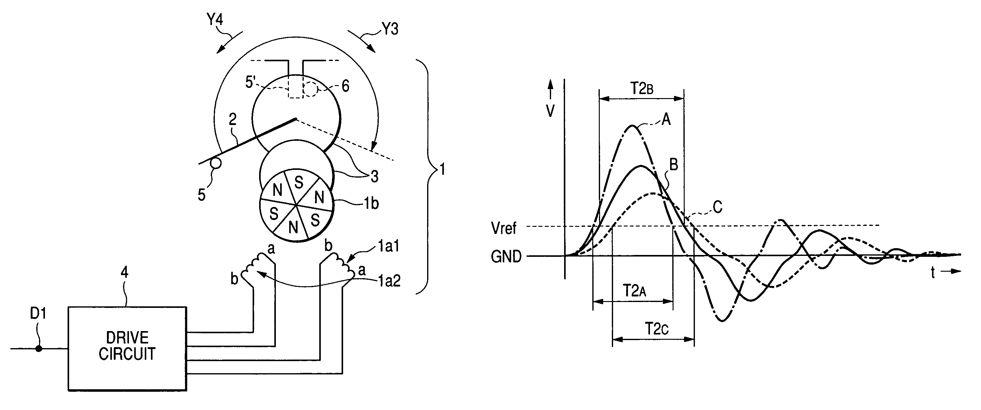
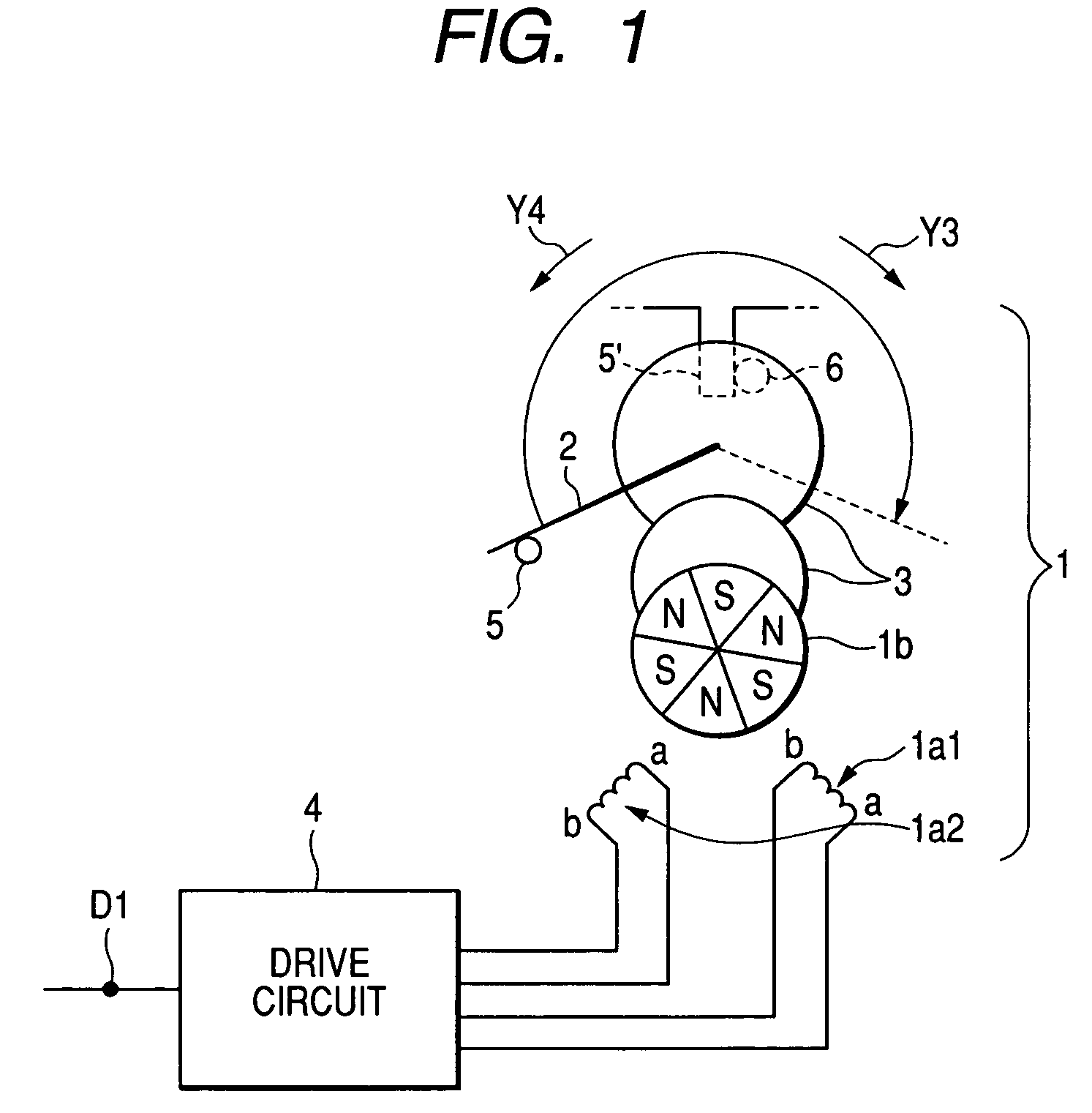
[0055]FIG. 1 is a configuration view of an on-vehicle meter using an embodiment of a stepper motor driving apparatus according to the invention. For example, the on-vehicle meter is a speed meter which has a stepper motor 1, and a drive circuit 4 for performing the drive control of the stepper motor 1. The stepper motor 1 includes two excitation coils 1a1 and 1a2 disposed on a stator (not shown) so as to be perpendicular to each other, and a rotor 1b which is magnetized so that three N poles and three S poles are arranged alternately and which rotates in accordance with change in excitation state of the excitation coils 1a1 and 1a2.

[0056]The on-vehicle meter further has an indicating pointer 2 provided as a driven member interlocked with the rotation drive of the rotor 1b, gears 3 for transmitting the rotation drive of the rotor 1b to the indicating pointer 2, and a stopper 5 for stopping the indicating pointer 2 in a zero position by contacting the indicating pointer 2 mechanically...


PUM


Abstract

A stepper motor driving apparatus, includes a stepper motor; a driven member interlocked with a rotation of a rotor of the stepper motor, a stopper stopping the driven member in a zero position, a controller controlling the excitation state of an excitation coil of the stepper motor, an induced voltage waveform detector detecting an induced voltage waveform generated on the basis of change of magnetic flux in accordance with the rotation of the rotor, and a zero position detector detecting whether the driven member is stopped in the zero position. The zero position detector includes a comparator which compares a time T2 in which each induced voltage waveform exceeds a predetermined threshold value with a predetermined contact determining reference time Tref, and a determinant which determines whether the driven member is stopped in the zero position by the stopper based on a result of the comparison by the comparator.

Description

BACKGROUND OF THE INVENTION[0001]The present invention relates to a stepper motor driving apparatus and particularly to a stepper motor driving apparatus improved in a process of initializing a stepper motor used in an on-vehicle meter or the like.[0002]For the reason of indication accuracy and cost, a stepper motor has been recently put into wide use in an on-vehicle meter such as a speed meter for indicating vehicle velocity or a tachometer for indicating the number of engine revolutions.[0003]In a vehicle equipped with an on-vehicle meter using such a stepper motor, there is however a possibility that a difference between the required amount of movement of an indicating pointer interlocked with the rotation of the stepper motor and the actual amount of movement of the indicating pointer may be generated by a mistaken drive signal caused by vibration of the vehicle, noise, etc.[0004]Therefore, in an on-vehicle meter using such a stepper motor, an initializing process is carried ou...

Claims


Application Information

Patent Timeline
Patent Type & Authority Patents(United States)
IPC IPC(8): H02P8/00G01R7/06H02P8/32G05B19/40H02P8/08H02P8/38
CPCG01R7/06G05B19/40H02P8/08G05B2219/41102G05B2219/41326G05B2219/41101G01D2213/10
Inventor YAMADA, YOSHIHISA
Owner YAZAKI CORP
Why Eureka
Try Eureka