
Converter for surface waves with improved suppression of interfering excitation

a technology of surface waves and transducers, applied in the direction of electrical transducers, generators/motors, impedence networks, etc., can solve the problems of increased insertion dampening, unwanted conductivity, draining signal energy, etc., and achieve the effect of improving insertion dampening

Inactive Publication Date: 2007-01-30
SNAPTRACK
View PDF15 Cites 12 Cited by
  • Summary
  • Abstract
  • Description
  • Claims
  • Application Information

AI Technical Summary

Benefits of technology

[0005]It is therefore the object of the present invention to specify a electro-acoustic transducer for a component operating with surface waves in which this loss mechanism is suppressed, and with whose help in particular surface wave filters can be produced that exhibit an improved insertion dampening.
[0020]In a further embodiment of the invention, the gaps are combined into groups that respectively in turn comprise at least two sub-groups. Each sub-group exhibits a sub-group pattern, formed from size and / or shape of the gaps and / or from the relative transversal position of the gaps within the sub-group. In each group, at least two different sub-group patterns are provided that occur alternately at least once per group. Moreover, each sub-group pattern can in turn exhibit a periodic variation with regard to at least one feature. In this manner, it is achieved to modulate the excitation in the gap region with at least two different functions that possess different periods. This leads to a multiple splitting of the interfering admittance, and therewith to a further improved suppression of the interfering signal in the excitation behavior of the inventive transducer.
[0023]As already mentioned, the properties of the transducer remain substantially unchanged by the variations in the gap region. This is achieved in that all the dimension changes in the variations of the gaps remain relatively small in comparison to the transducer finger length. A completely sufficient effect is achieved when the dimension change in the variation of the gaps amounts to double the finger width of a transducer finger. The variation thereby lies far below the variations that are used to weigh the transducer, and to form the transfer function of the transducer. In contrast, with the invention even the admittance of the transducer should remain unchanged and only be reduced by the interfering excitation, which has nothing to do with the desired excitation. Completely without reciprocal action on the excitation function, a variation of the gaps remains that is only achieved via variation of the stump fingers. The overlapping length of the transducer fingers can be kept unchanged, and in particular be held constant over the transducer length. However, it is also possible to combine the variation with regard to the gaps with a normal phase weighting or omission weighting.
[0029]An inventive transducer can comprise a metallization made from a uniform material, in particular from aluminum and its alloys. However, it is also possible to fashion the transducer from a plurality of layers, whereby at least one part of the individual layers comprises aluminum as at least the main component. The remaining layers can be fashioned from Cu, Mg, Ti, Zr, Sc or also other metals. In this manner, a high stability of the transducer is achieved when an electrical signal with high power is coupled and is transduced into a surface wave.
[0030]Inventive transducers are not limited to uniform finger periods. Inventive transducers can therefore also exhibit increasing or decreasing finger widths and / or finger separations (=finger periods) in the longitudinal direction. Such transducers are also referred to as chirped transducers. Due to the periodicity changing over the transducer length, such a transducer exhibits an increased bandwidth.

Problems solved by technology

A real portion (differing there from zero) of the input admittance of the parallel resonator namely leads to an unwanted conductivity in the transmission range, to a drain of the signal energy, and to an increased insertion dampening.
The input admittance of a single-port resonator typically used today now shows precisely a shoulder in this range, that therewith leads to an increased input dampening in a reactance filter.
However, for this or also even for other known shoulders, as of yet no measures are known in order to effectively suppress them.

Method used


Image

  • Converter for surface waves with improved suppression of interfering excitation
  • Converter for surface waves with improved suppression of interfering excitation
  • Converter for surface waves with improved suppression of interfering excitation

Examples


Embodiment Construction

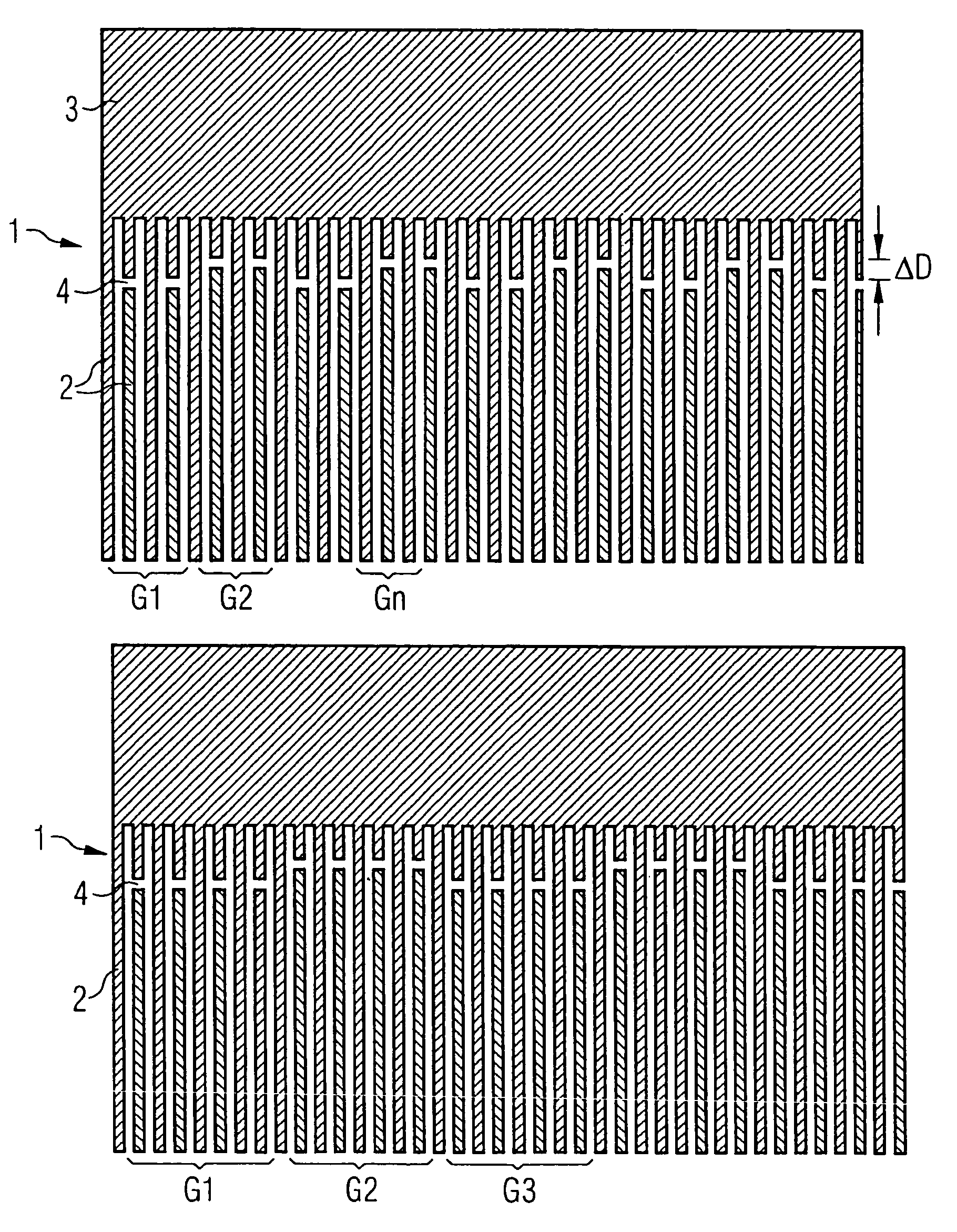
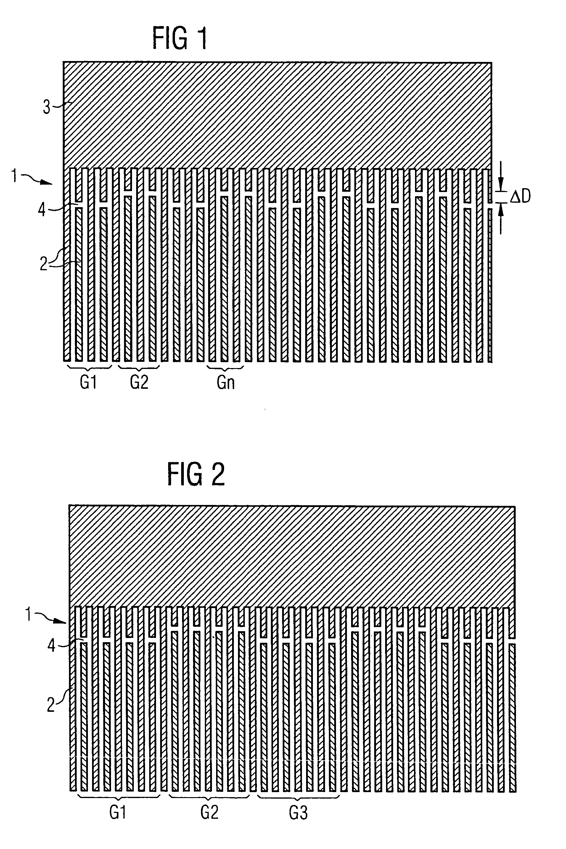
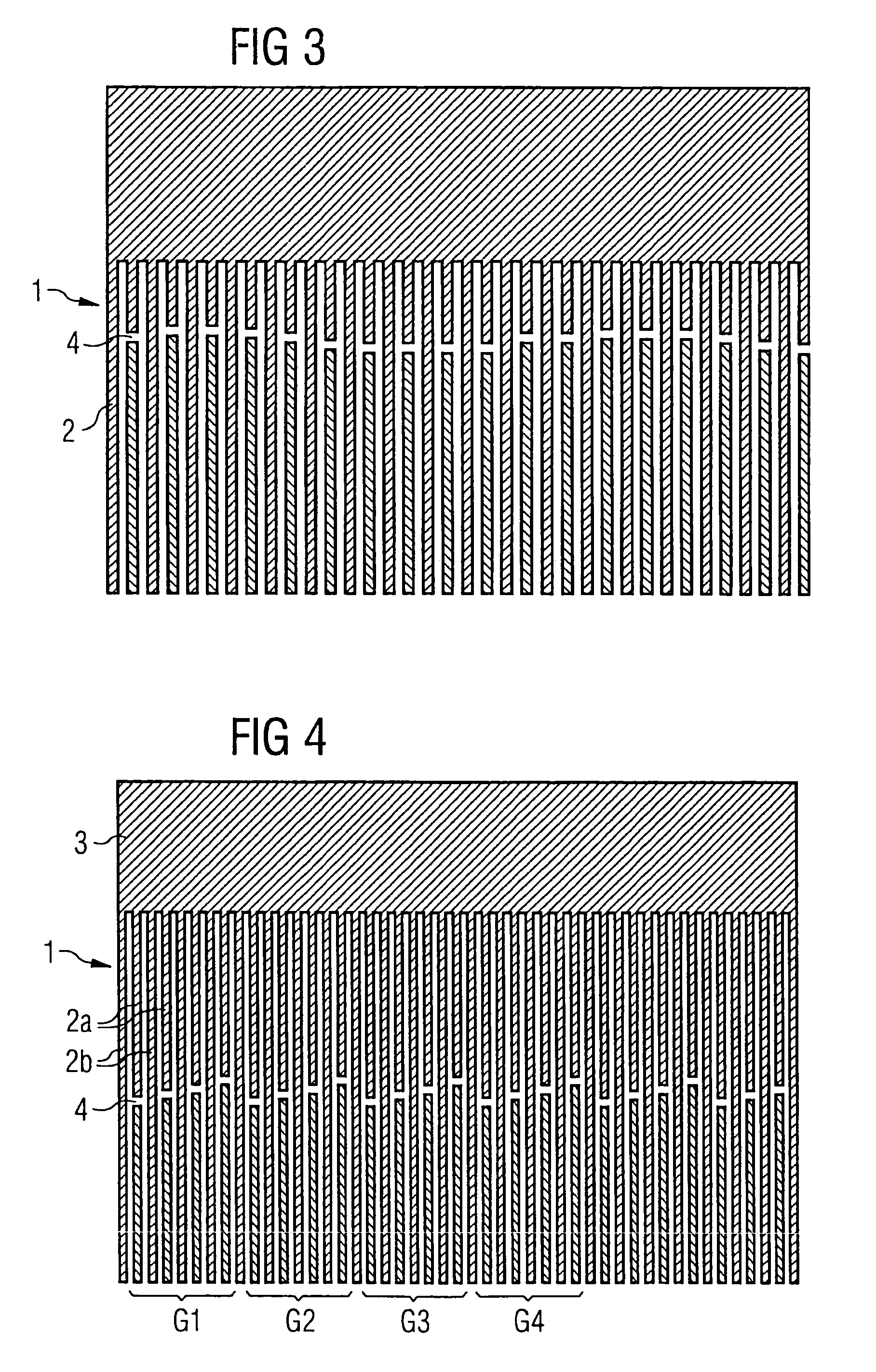
[0046]FIG. 1 shows a simple embodiment of the invention. Shown section-by-section is a normal finger transducer 1 in the area of a busbar 3. This transducer comprises two electrode fingers 2 per wavelength. In this embodiment, the transducer is varied with regard to the transversal gap position. The absolute amount ΔD by which the gaps 4 are maximally displaced here amounts to less than two electrode finger widths (in a normal finger transducer thus less than a distance that corresponds to half a excitation light at middle frequency). Via displacement in pairs of two respectively adjacent gaps opposite the two respectively adjacent pairs of gaps, the interfering excitation in the gap region is multiplied in the time domains with a further excitation function that has a period of four SAW (Surface Acoustic Wave) wavelengths. A folding in the frequency range thereby results, and a splitting of the excitation, which thereby disappears from the stop band range.

[0047]FIG. 2 likewise show...


PUM


Abstract

An electro-acoustic transducer for a component operating with surface waves, in particular for a surface wave filter, in which, to suppress interfering excitation ensuing in the gap region adjacent an end of a finger, a variation of the gaps is implemented with regard to at least one feature selected from transversal arrangement, size and shape. Due to the slight dimension change of the position of the gap in comparison to the finger length, the desired primary excitation in the transducer remains approximately unchanged, however the interfering excitation is displaced or divided, and made ineffectual.

Description

BACKGROUND OF THE INVENTION[0001]A surface wave component comprises at least one electro-acoustic transducer that is arranged on a crystalline or ceramic piezoelectric thin film. The electro-acoustic transducer possesses a periodic finger structure, whereby the fingers are as a rule alternately connected to two different collector electrodes (busbars). The period of the finger structure determines the resonance frequency of the transducer, which corresponds to the frequency in which the electro-acoustic conversion ensues with the greatest degree of efficiency. Given a surface wave resonator, the impedance of the resonator is approximately zero at the resonance frequency.[0002]The important properties of the transducer are substantially determined by number, width, separation and connection sequence of the electrode fingers, as well as by the aperture of the transducer. These are, as a rule, selected such that, as exclusively as possible, only an acoustic vibration mode is excited, o...

Claims


Application Information

Patent Timeline
Patent Type & Authority Patents(United States)
IPC IPC(8): H03H9/00H01L41/09H03H9/02H03H9/145H03H9/42H03H9/64
CPCH03H9/02992H03H9/14547H03H9/14544H03H9/1452
Inventor RUILE, WERNERBAUER, THOMASJAKOB, MICHAELROSLER, ULRIKE
Owner SNAPTRACK
Learn More