Pure Dielectric Antennas and Related Devices

a dielectric antenna and dielectric technology, applied in the direction of antennas, antenna details, basic electric elements, etc., can solve the problem of complex radiation mechanism, and achieve the effect of high radiation efficiency

Inactive Publication Date: 2007-11-01
MICROSOFT TECH LICENSING LLC +1
View PDF5 Cites 32 Cited by
  • Summary
  • Abstract
  • Description
  • Claims
  • Application Information

AI Technical Summary

Benefits of technology

[0031] iii) They have extremely high radiation e...

Problems solved by technology

Here the radiation mechanism is thought to be more complex as the groundplane plays a...

Method used


Image

  • Pure Dielectric Antennas and Related Devices
  • Pure Dielectric Antennas and Related Devices
  • Pure Dielectric Antennas and Related Devices

Examples


Embodiment Construction

1) Purely Dielectric Dipoles and Other Balanced Antennas

[0065] A description of the basic technology will now be given using as an example a purely dielectric dipole antenna of a first variation of embodiments of the present invention.

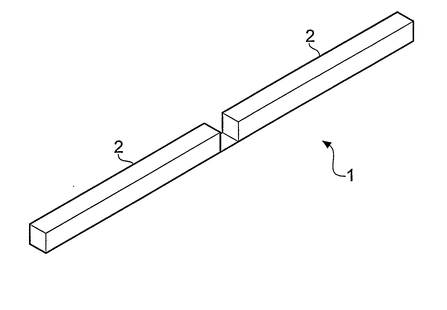
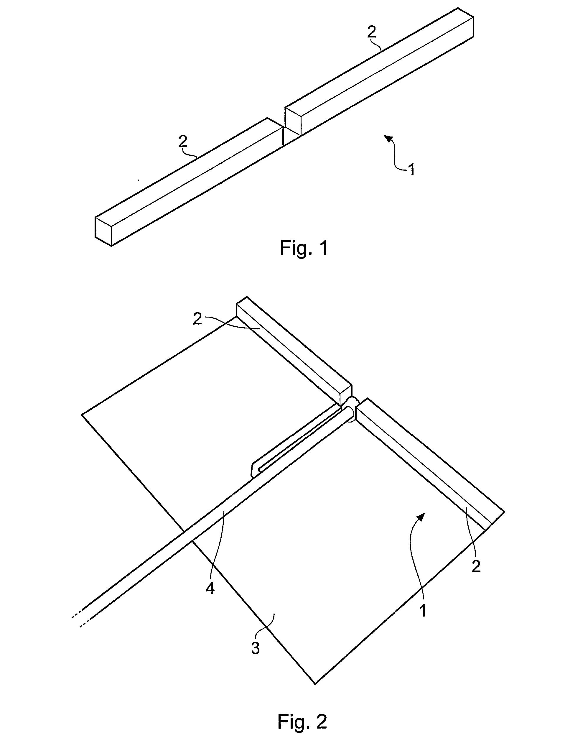
[0066]FIG. 1 shows a simulated ceramic dipole 1 in free-space, the dipole having a pair of co-linear radiating arms 2.

[0067]FIG. 2 shows a practical realization of the concept shown in FIG. 1, in the form of a dipole 1 comprising a pair of oblong dielectric ceramic elements 2 mounted along a line on a Duroid® substrate 3 (εr≈2.2) with a micro-strip balun 4.

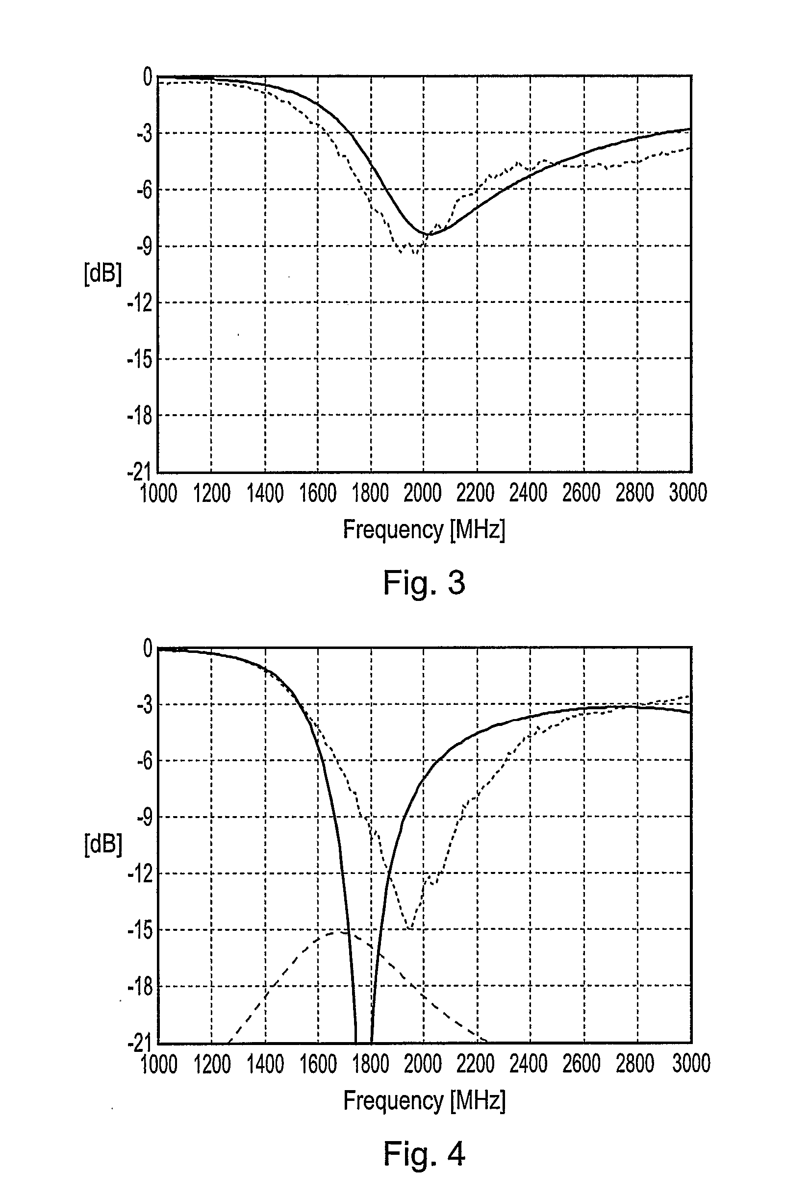
[0068]FIG. 3 shows the matched return loss—calculated (solid line) and measured (dashed line) for the embodiments of FIGS. 1 and 2 respectively, while FIG. 4 shows the unmatched return loss plots.

[0069] For this antenna it has been found that increasing the dimensions causes a decrease in resonant frequency exactly in inverse proportion. Thus an antenna with a dielectric constant (εr) of 135 and...


PUM


Abstract

There is disclosed an antenna device comprising an elongate dielectric radiating element having a longitudinal axis and a feeding mechanism for generating displacement currents in the dielectric radiating element. The radiating element is configured to support displacement current resonance modes parallel to the longitudinal axis but to inhibit displacement current resonance modes transverse to the longitudinal axis.

Description

[0001] The present invention relates to novel antennas, in particular for RF applications, in which an elongate substantially purely dielectric component supports a novel mode of resonance. BACKGROUND [0002] The present applicant has developed a new type of antenna technology that is based on substantially purely dielectric materials and yet which is believed to be different from both dielectric resonator antennas (DRAs) and electrically conductive antennas. Electrically conductive antennas such as dipoles can be almost infinitely thin if conductivity is sufficiently good, whereas the substantially purely dielectric antennas of embodiments of the present invention need a finite cross-section to radiate effectively. DRAs are volume devices that radiate like a cavity. It is not clear whether a DRA would turn into a purely dielectric antenna if it was made to be so long and thin that transverse resonant modes were no longer possible (at the frequencies of interest) because this subject...

Claims


Application Information

Patent Timeline
IPC IPC(8): H01Q1/38H01Q9/04H01Q9/36
CPCH01Q9/36H01Q9/0485H01Q9/04
Inventor IDE, JONATHANKINGSLEY, SIMON PHILIPO'KEEFE, STEVEN GREGORYSAARIO, SEPPO
Owner MICROSOFT TECH LICENSING LLC
Why Eureka
Try Eureka