Tamper switch structure and security sensor including the tamper switch structure

a technology of tamper switches and switches, applied in the direction of burglar alarm mechanical actuation, instruments, electric signalling details, etc., can solve the problems of poor operability of the intruder detection system, sensor will not be able to detect illegal intruders, and the detection of illegal intruders is disabled

Active Publication Date: 2007-01-30
OPTEX CO LTD
View PDF8 Cites 16 Cited by
  • Summary
  • Abstract
  • Description
  • Claims
  • Application Information

AI Technical Summary

Benefits of technology

[0021]With this feature, in a state in which the security sensor is fixed to a fixed object surface to which the security sensor is fixed, the elastic switch member elastically deforms by receiving a pushing force from the fixed object surface, and depresses the switch actuating member, while maintaining the closed state of the above-described tamper opening. Thus, the tamper switch body recognizes that the security sensor is fixed to the fixed object surface, and therefore does not transmit the tampering detection signal (trouble signal). Even if this security sensor is installed outside and rainwater or the like pours over it, rainwater or the like will not enter into the housing of the security sensor, since the tamper opening is maintained in a closed state by the elastic switch member. Then, the security sensor has been removed from the fixed object surface in an attempt of illegal intrusion or the like, the pushing force received by the elastic switch member from the fixed object surface to which the security sensor is fixed is released, and the elastic switch member is restored in a shape to which no external force is applied, releasing the depressing of the switch actuating member. Thus, the tamper switch body recognizes that the security sensor has been removed from the fixed object surface to which the security sensor has been fixed, and therefore transmits the tampering detection signal (trouble signal). In this way, in this solving means, the elastic switch member that depresses the switch actuating member by elastically deforming by the pushing force from the fixed object surface to which the security sensor is fixed is mounted in the tamper opening of the housing. Accordingly, it is possible to prevent a flood into the security sensor by rain or the like, while providing the security sensor with the tampering detection function, thus making it possible to realize outdoor installation of the security sensor having the tampering detection function.
[0022]A specific configuration of the elastic switch member in this case may include a sealing portion, a pressure-receiving projection portion and an actuating projection portion. The sealing portion is a portion that seals the inside of the housing by contacting an inner surface of the tamper opening to close the tamper opening. The pressure-receiving projection portion is a portion that is integrally formed with the sealing portion and that receives a pushing force from the fixed object surface to which the security sensor is fixed in a fixed state. The actuating projection portion is a portion that is integrally formed with the sealing portion and that applies a pushing force in a depressing direction to the switch actuating member of the tamper switch body through elastic deformation of the sealing portion by the pressure-receiving projection portion receiving a pushing force from the fixed object surface to which the security sensor is fixed in a fixed state. That is, in this elastic switch member, the sealing portion elastically deforms, while sealing the inside of the housing by closing the tamper opening, thereby allowing the pushing force received by the pressure-receiving projection portion from the fixed object surface to which the security sensor is fixed to be acted upon the switch actuating member of the tamper switch body via the actuating projection portion. Accordingly, it is possible to perform a highly reliable tampering detection operation.
[0024]In the case of this solving means, in a state in which the second cover is mounted on the first cover, the elastic switch member elastically deforms by receiving a pushing force from the second cover, thereby rendering the switch actuating member in a depressed state, while maintaining the closed state of the above-described tamper opening. Thus, the tamper switch body recognizes that the second cover is mounted on the first cover, and therefore does not transmit the tampering detection signal (trouble signal). Even if this security sensor is installed outside and water enters the gap between the first cover and the second cover because of rainwater or the like pouring over it, rainwater or the like will not enter into the housing (into the first cover) of the security sensor, since the above-described tamper opening is maintained in a closed state by the elastic switch member. Then, when the second cover has been removed from the first cover in an attempt of illegal intrusion or the like, the pushing force received by the elastic switch member from the second cover is released, and the elastic switch member is restored in a shape to which no external force is applied, releasing the depressing of the switch actuating member. Thus, the tamper switch body recognizes that the second cover has been removed from the first cover, and therefore transmits the tampering detection signal (trouble signal). In this way, also with this solving means, it is possible to prevent a flood into the sensor by rain or the like, while providing the security sensor with the tampering detection function, thus making it possible to realize outdoor installation of the security sensor having the tampering detection function.
[0025]In a specific configuration of the elastic switch member in this case, the elastic switch member may be connected with the switch actuating member of the tamper switch body via a connection pin, and may include a sealing portion and a pressure-receiving projection portion. The sealing portion is a portion that seals the inside of the housing by contacting an inner surface of the tamper opening to close the tamper opening. The pressure-receiving projection portion is a portion that is integrally formed with the sealing portion and that receives a pushing force from the second cover in a mounted state of the second cover. The back surface of the pressure-receiving projection portion applies an operational force to the connection pin through elastic deformation of the sealing portion by the pressure-receiving projection portion receiving a pushing force from the second cover in a mounted state of the second cover, and the connection pin applies a pushing force in a depressing direction to the switch actuating member. That is, even if the distance between the elastic switch member and the switch actuating member is large, the depressing force for deforming the elastic switch member can be acted upon the switch actuating member via the connection pin, thus making it possible to perform a highly reliable tampering detection operation also in this case. Furthermore, it is possible to increase the flexibility of the setting position of the tamper switch body within the housing.
[0026]Further, in the case of applying the present invention to a security sensor provided with a plurality of casing members that are combined one another to form the housing, the above-described elastic switch member may be integrally formed with a seal member disposed in an adjacent surface portion where the casing members are in contact with each other. That is, it is possible, with a single member, to achieve a sealed structure for preventing a flood between the casing members and a sealed structure for preventing a flood into the housing by closing the tamper opening, thus reducing the number of parts of the sensor as a whole.
[0028]As described above, according to the present invention, the elastic switch member at a position opposite the switch actuating member of the tamper switch is provided with both the function of ensuring sealing for preventing a flood into the housing and the function of an actuating member for tempering detection. Accordingly, it is possible to prevent a flood into the sensor by rain or the like, while providing the security sensor with the tampering detection function, thus making it possible to realize outdoor installation of the security sensor having the tampering detection function and to improve the usefulness of the outdoor installation type security sensor.

Problems solved by technology

On the other hand, in an attempt to illegally intrude into a room in which this type of sensor is installed, the sensor body may be removed from the mounting plate in non-alert operation, and be mounted on the mounting plate again after the sensor is rendered unable to detect a human body by corrupting it (tampering) such as attaching paper tape or plastic tape or spraying transparent paint that does not transmit infrared radiation onto the incident path of infrared radiation to the PIR element within the sensor body.
In this case, the sensor will not be able to detect illegal intruders in alert operation.
Also, the sensor body may be removed from the mounting plate in non-alert operation and stolen, so that the detection of illegal intruders is disabled.
In the case of providing such a tampering detection function, it is necessary to provide a large number of wiring, namely, power supply wiring, transmission wiring for a human body detection signal for sending a detection signal at the time of detecting a human body and wiring for tampering detection, between the mounting plate on which the sensor body is mounted and a control panel that is placed at a different location, resulting in a poor operability of the intruder detection systems.
Conventional security sensors such as the PIR sensor have required relatively large power consumption, and thus have required the above-described power supply wiring.
The fact that the power supply wiring becomes unnecessary in this way can lead to that it is impossible to realize the above-described configuration, such as that “allows the detection of disconnection of the power supply wiring, thereby making it possible to detect the stealing”.
When the sensor has been removed from the wall surface or when the sensor body has been removed from the mounting plate, the depressing of the actuating piece is released, and as a result, the trouble signal is transmitted.
As described above, although the type of security sensors to which the power supply wiring is connected can detect the above-described stealing by allowing the detection of disconnection of the power supply wiring, they cannot detect the tampering such as attaching paper tape or plastic tape or spraying transparent paint that does not transmit infrared radiation onto the incident path of infrared radiation without disconnecting the power supply wiring.
Therefore, in the case of using this type of security sensor as the outdoor installation type, the tamper switch structure disclosed in Patent reference 1 above cannot be used as it is.
The reason is that, since rainwater or the like may poured over security sensors installed outdoor, rainwater or the like may enter the structure disclosed in Patent reference 1 above from the opening provided for projecting the actuating piece of the tamper switch, causing a failure of the sensor.

Method used


Image

  • Tamper switch structure and security sensor including the tamper switch structure
  • Tamper switch structure and security sensor including the tamper switch structure
  • Tamper switch structure and security sensor including the tamper switch structure

Examples


Embodiment Construction

[0037]Hereinafter, an embodiment of the present invention will be described with reference to the accompanying drawings. In this embodiment, a case will be described where the present invention is applied to a security PIR sensor serving as a starting switch of a security alarm device.

[0038]Overall Configuration of PIR Sensor

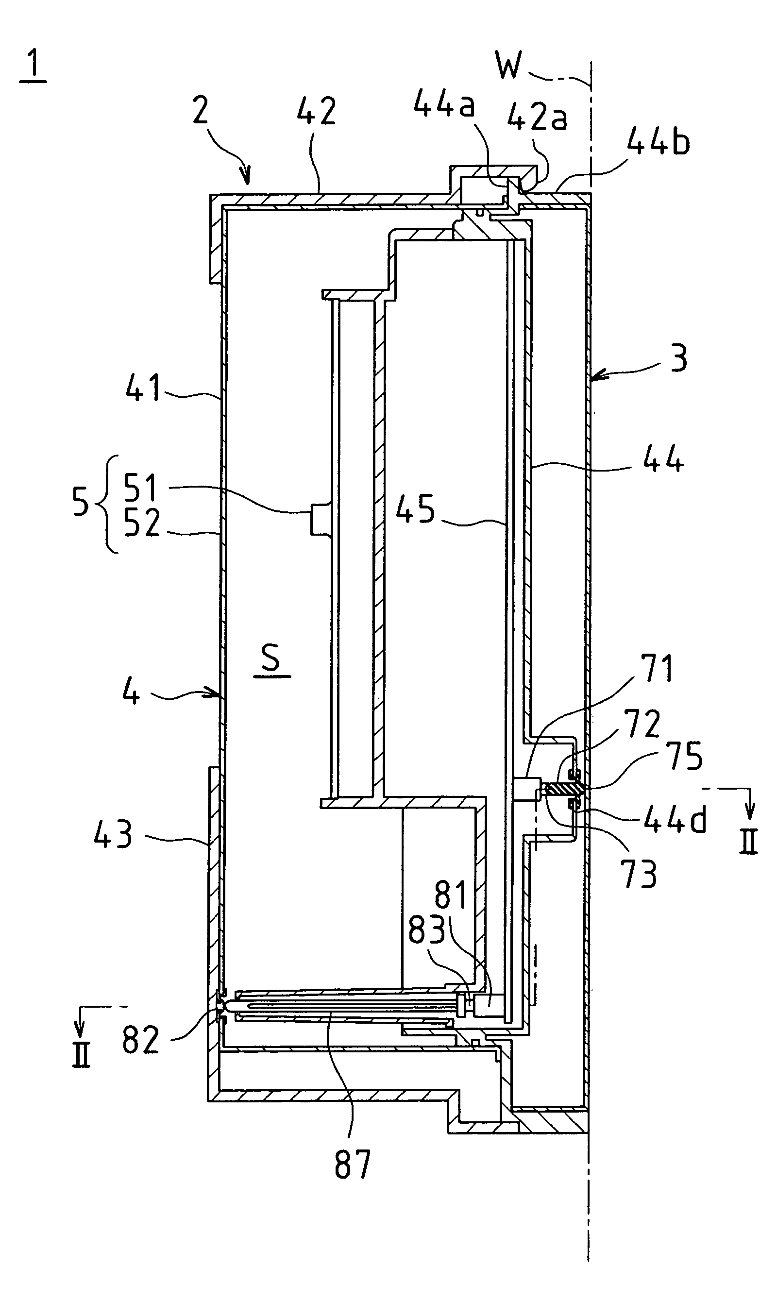
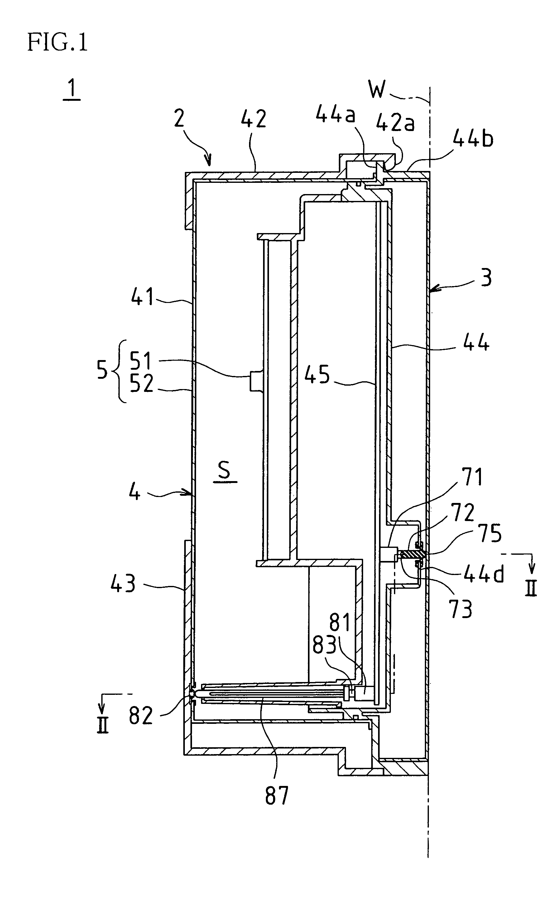
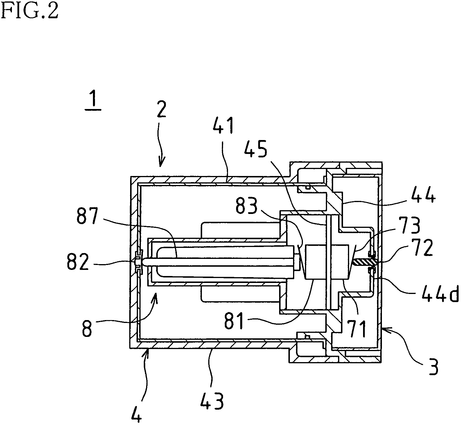
[0039]FIG. 1 is a vertical cross-sectional view schematically showing the internal configuration of a PIR sensor 1 according to this embodiment. FIG. 2 is a cross-sectional view of the PIR sensor 1, taken at the position corresponding to the line II—II in FIG. 1.

[0040]As shown in FIGS. 1 and 2, the PIR sensor 1 of this embodiment is mounted on an outer wall surface W (see the dash-dotted line in FIG. 1) of a house or an office building, and includes a sensor body 2 and a mounting plate 3. That is, after the mounting plate 3 is fixed to the above-described outer wall surface W, the sensor body 2 is fixed to the mounting plate 3, and thereby the PIR sensor is fixe...


PUM


Abstract

A tamper switch body is disposed in a housing of a PIR sensor. A tamper opening is formed at a position opposite a switch actuating member of the tamper switch body in a base plate of the PIR sensor. An elastic switch member is mounted in the tamper opening. The elastic switch member includes a pressure-receiving projection portion abutting a mounting plate, and depresses the switch actuating member through elastic deformation of the pressure-receiving projection portion by receiving a pushing force from the mounting plate in a state in which the PIR sensor is fixed to a wall surface. The elastic switch member seals the inside of the housing by closing the tamper opening, thus preventing a flood into the housing of the PIR sensor.

Description

BACKGROUND OF THE INVENTION[0001]1. Field of the Invention[0002]This application claims priority under 35 U.S.C. § 119(a) on Patent Application No. 2004-88999 filed in Japan on Mar. 25, 2004, the entire contents of which are hereby incorporated by reference.[0003]The present invention relates to tamper switch structures used for security sensors such as passive infrared sensors (PIR sensors) and active infrared sensors (AIR sensors), and to security sensors including such tamper switch structures. In particular, the invention relates to measures for adding a tampering detection function to security sensors of outdoor installation type (the type installed at locations where water such as rainwater pours over) with a simple configuration.[0004]2. Description of the Related Art[0005]Conventionally, the PIR sensor, which is one type of security sensors, contains a PIR element, and is so configured that this PIR element detects an intruder from the difference between the temperature of t...

Claims


Application Information

Patent Timeline
Patent Type & Authority Patents(United States)
IPC IPC(8): G08B29/00G08B13/00G08B13/14G08B13/191G08B29/04H01H3/16H01H9/04
CPCG08B29/046G08B13/149
Inventor NOGUCHI, MICHINORI
Owner OPTEX CO LTD
Why Eureka
Try Eureka