Navigation system incorporating antenna

a navigation system and antenna technology, applied in the direction of navigation instruments, electric apparatus casings/cabinets/drawers, instruments, etc., can solve the problems of insufficient directivity, difficult to reduce the size of the receiver, and insufficient directivity, etc., to achieve convenient installation in the vehicle, improve the effect of installationability

Inactive Publication Date: 2007-01-30
DENSO CORP
View PDF9 Cites 3 Cited by
  • Summary
  • Abstract
  • Description
  • Claims
  • Application Information

AI Technical Summary

Benefits of technology

[0005]The present invention therefore has an objective to provide a navigation system incorporating an antenna, directivity of which is properly secured, with improved installability. A navigation system of the present invention includes an antenna element integrated to a cabinet, a part of which is made of metal and finished to function as a ground of the antenna element. Since the antenna is integrated to the cabinet, wiring of the antenna can be arranged inside the cabinet. Namely, wiring of the antenna outside the cabinet can be eliminated and therefore the navigation system is easily installed in a vehicle.

Problems solved by technology

Thus, an area occupied by the antenna is large, which makes difficult to reduce the size of the receiver.
However, such a ground is not provided in the receiver and proper directivity is not secured.

Method used


Image

  • Navigation system incorporating antenna
  • Navigation system incorporating antenna
  • Navigation system incorporating antenna

Examples


first embodiment

[0012][First Embodiment]

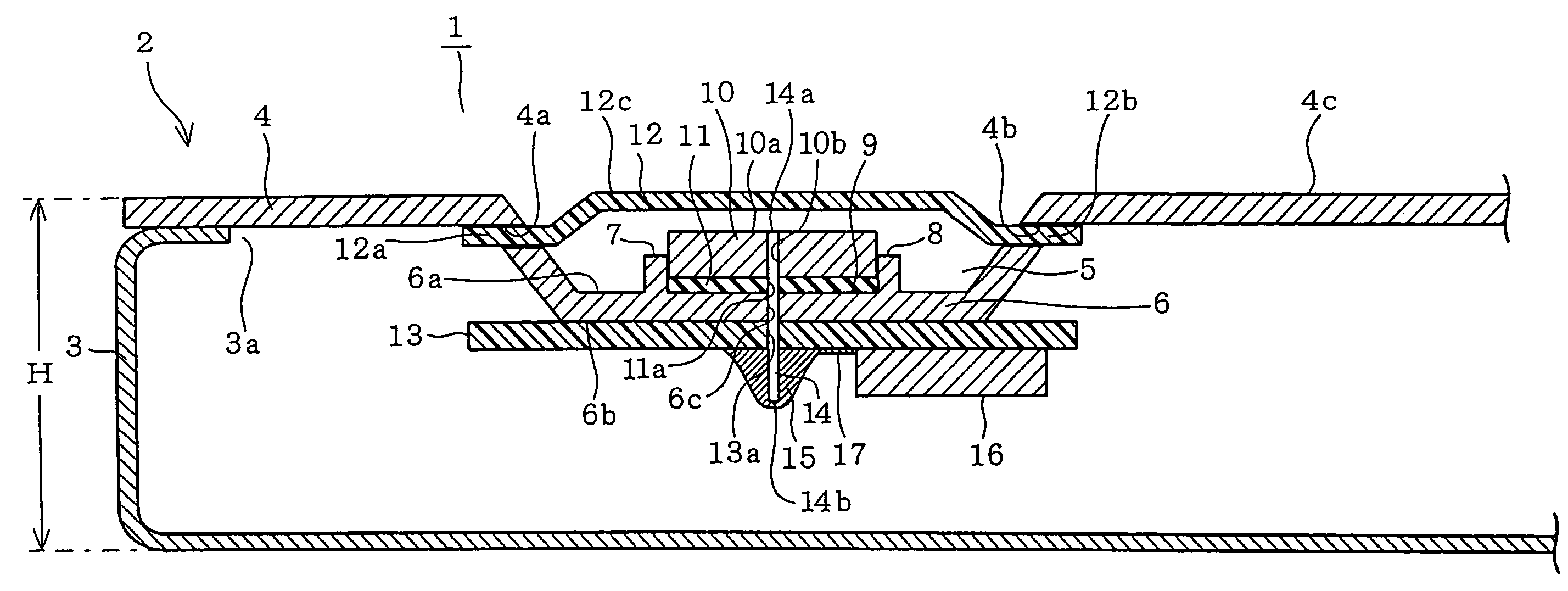
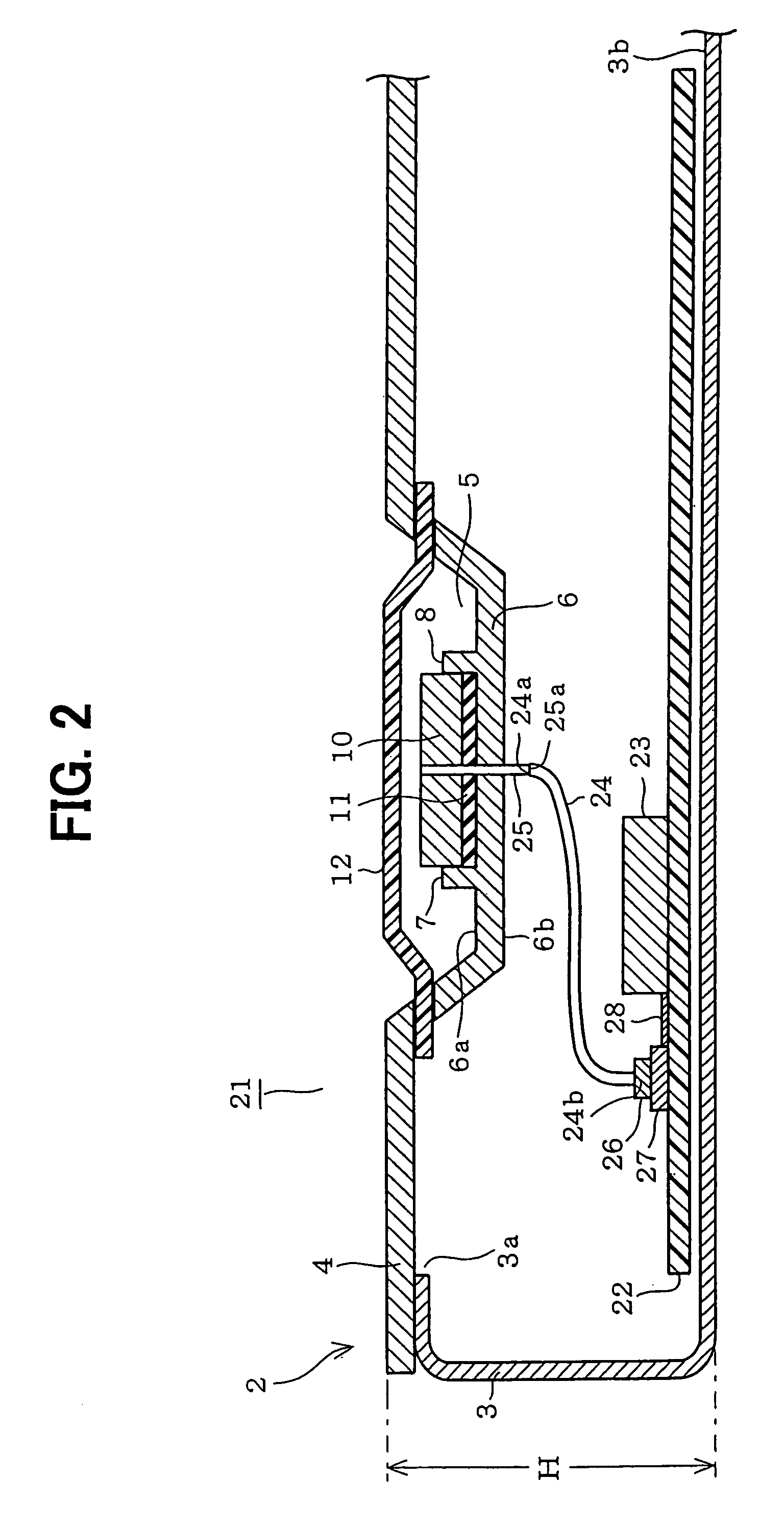
[0013]Referring to FIG. 1, a navigation system 1 incorporating an antenna includes a cabinet 2. The cabinet 2 is constructed of a case 3 and a cover 4, both made of metal and electroplated, and its overall shape is a substantially rectangular box. The case 3 is formed in an open-top box shape with an opening 3a that is closed with the cover 4 after a printed circuit board (PCB) and other electronic parts are placed in the case 3. A height H of the cabinet 2 is slightly smaller than an inside height of a Deutsche Industrie-Norm (DIN) slot so that the cabinet 2 is fit in the DIN slot.

[0014]The cover 4 has a recess 5 in a predetermined area for holding an antenna element 10. An antenna element mounting portion 9 is formed by ribs 7, 8 on a top surface 6a of a bottom 6 of the recess 5. The antenna element 10 is formed substantially in a rectangular or square box shape and fixed to the antenna element mounting portion 9 via a double-faced tape 11. It receives GPS ...

second embodiment

[0023][Second Embodiment]

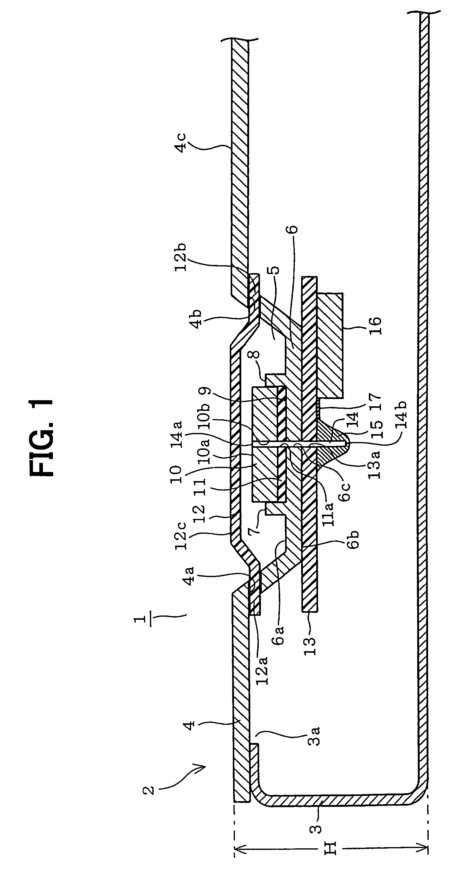
[0024]Referring to FIG. 2, a navigation system 21 includes a PCB 22 arranged along a bottom 3a of the case 3 inside the cabinet 2. In FIG. 2, parts indicated with the same numerals as the first embodiment shown in FIG. 1 are the same parts in the first embodiment. Therefore, detailed descriptions for those parts will not be provided here. A high-frequency IC 23 having the same function with the high-frequency IC 16 of the first embodiment is mounted on the PCB 22 at a predetermined position. The first end 24a of a coaxial cable 24 is connected with the first end 25a of a power supply pin 25 and the second end 24b of the coaxial cable 24 is connected with a connector 26. A connector 27 is connected with the connector 26 and the PCB 22. As a result, the antenna element 10 is electrically connected with the high-frequency IC 23 via the power supply pin 25, the coaxial cable 24, the connectors 26, 27, and a wiring pattern 28 on the PCB 22.

[0025]In the navigation...

third embodiment

[0027][Third Embodiment]

[0028]Referring to FIG. 3, a navigation system 31 includes a high-frequency IC 35 arranged adjacent to the antenna element 10. In FIG. 3, parts indicated with the same numerals as the first embodiment shown in FIG. 1 are the same parts in the second embodiment. Therefore, detailed descriptions for those parts will not be provided here.

[0029]In a navigation system 31 incorporating an antenna, a cover 32 has a recess 33, a bottom area of which is larger than that of the recess 5 provided in the cover 4 of the first or the second embodiment. The cover 32 is made of metal and electroplated and formed such that its surface area is larger than that of an antenna element 34 and electrically connected with the antenna element 34. The cover 32 is a ground of the antenna element 34. The antenna element 34 is a surface mount-type element and mounted on a sub PCB 36.

[0030]A high-frequency IC 35 having the same function as the high-frequency IC 23 of the second embodiment...


PUM


Abstract

A navigation system incorporating an antenna includes a cabinet constructed of electroplated case and cover. An antenna element is integrated to the cabinet and electrically connected with the cover that is a ground of the antenna element. With this configuration, the cabinet and the antenna element can be installed in a vehicle at once and wiring of the antenna element outside the cabinet can be eliminated. Thus, installability of the navigation system is improved in comparison with known devices. Furthermore, the cover is formed such that its surface is larger than that of the antenna element. As a result, directivity of the antenna element is properly secured.

Description

CROSS REFERENCE TO RELATED APPLICATION[0001]This application is based on and incorporates herein by reference Japanese Patent Application No. 2003-322939 filed on Sep. 16, 2003.FIELD OF THE INVENTION[0002]The present invention relates to a navigation system incorporating an antenna.BACKGROUND OF THE INVENTION[0003]A receiver incorporating an antenna is proposed in JP-A-6-237188. The antenna is integrated into a cabinet and therefore wiring of the antenna outside the cabinet can be eliminated. Installability of the antenna is improved by providing the antenna and the cabinet as a unit and eliminating the wiring outside the cabinet.[0004]In this receiver, the antenna is provided as a flat antenna printed on a printed circuit board. Thus, an area occupied by the antenna is large, which makes difficult to reduce the size of the receiver. Moreover, a ground having a larger area than the antenna is required for securing proper directivity. However, such a ground is not provided in the rec...

Claims


Application Information

Patent Timeline
Patent Type & Authority Patents(United States)
IPC IPC(8): H05K5/00H01Q1/38G01C21/00G01C21/20G01C21/26G01S1/00G01S19/36G08G1/0962H01Q1/22H01Q1/32H01Q1/42H01Q1/52H01Q3/00H01Q13/08
CPCG01C21/26G01S19/36H01Q1/526H01Q1/38H01Q1/42H01Q1/3291G01C21/20
Inventor NAKABUCHI, MASAYUKI
Owner DENSO CORP
Why Eureka
Try Eureka