Drive apparatus for electric vehicle

a technology for electric vehicles and drive apparatuses, which is applied in the direction of electric propulsion mounting, transportation and packaging, windings, etc., can solve the problems of reducing the diameter of the stator, limiting the maximum height of the entire rotating electric device that can still fit in the vehicle, and reducing the output of the rotating electric device, so as to achieve the effect of easy installation in the vehicle, improved output of the drive apparatus, and easy detection

Active Publication Date: 2010-03-16
TOYOTA JIDOSHA KK
View PDF21 Cites 0 Cited by
  • Summary
  • Abstract
  • Description
  • Claims
  • Application Information

AI Technical Summary

Benefits of technology

[0011]It is an object of the invention to provide a drive apparatus for an electric vehicle, which can be easily installed in a vehicle.
[0013]With the aforementioned configuration, the height of the rotating electric device housing can be reduced, and the rotating electric device can be installed in a vehicle more easily. Also, the increase in the outer diameter of the rotating electric device can be easily minimized.
[0015]With the aforementioned configuration, even if the axial length of the stator is changed, the shapes of the first terminal and the second terminal do not need to be changed. As a result, the number of additional components that may be needed in the rotating electric device is minimized.
[0017]The above configuration forms a more secure seal in the rotating electric device. Also, when the terminal block is fitted, the seal portion is fitted after the initial stage of the process for fitting the first terminal to the second terminal is completed. Therefore, fitting of the first terminal to the second terminal can be easily detected.
[0018]One aspect of the invention provides a compact drive apparatus for an electric vehicle. Also, the drive apparatus can be installed in the vehicle easily, and the output of the drive apparatus can be improved.

Problems solved by technology

However, due to space constraints in a vehicle, there is a limit to the maximum height of the entire rotating electric device that can still fit in the vehicle.
However, reducing the diameter of the stator decreases the output of the rotating electric device.

Method used


Image

  • Drive apparatus for electric vehicle
  • Drive apparatus for electric vehicle
  • Drive apparatus for electric vehicle

Examples


Embodiment Construction

[0026]Hereinafter, a drive apparatus for an electric vehicle according to an example embodiment of the invention will be described. The same or corresponding portions are denoted by the same reference numerals, and redundant description thereof will be omitted.

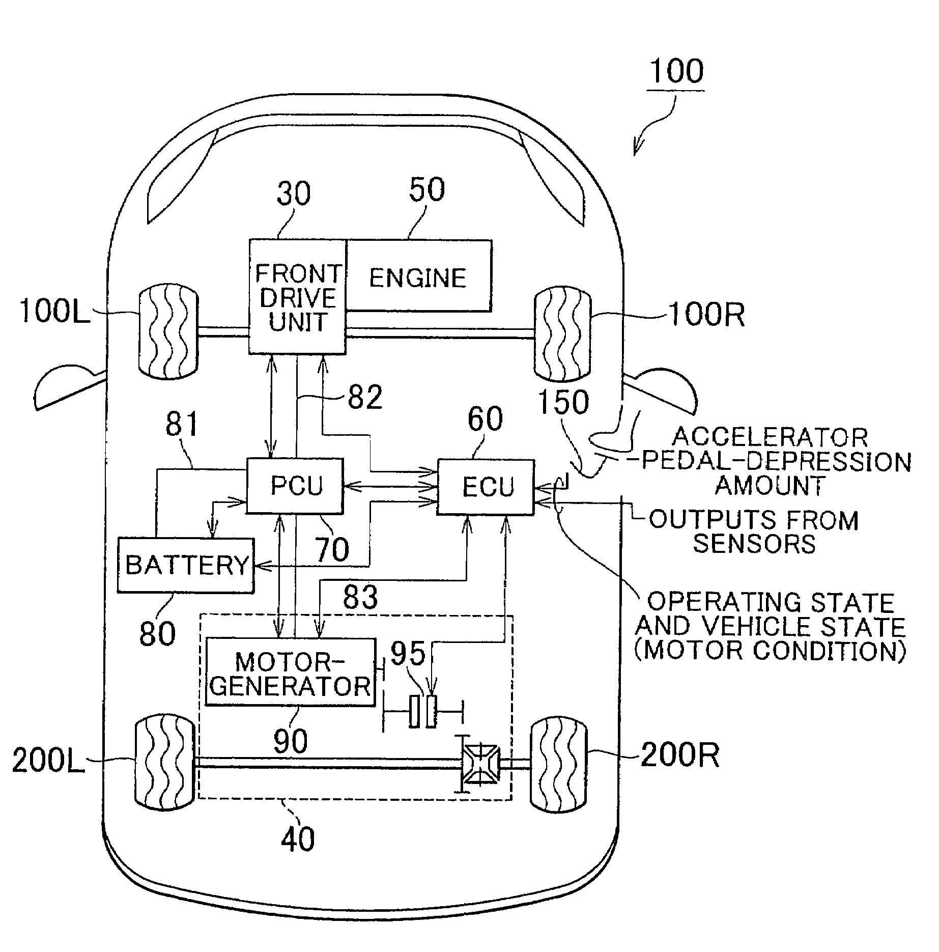
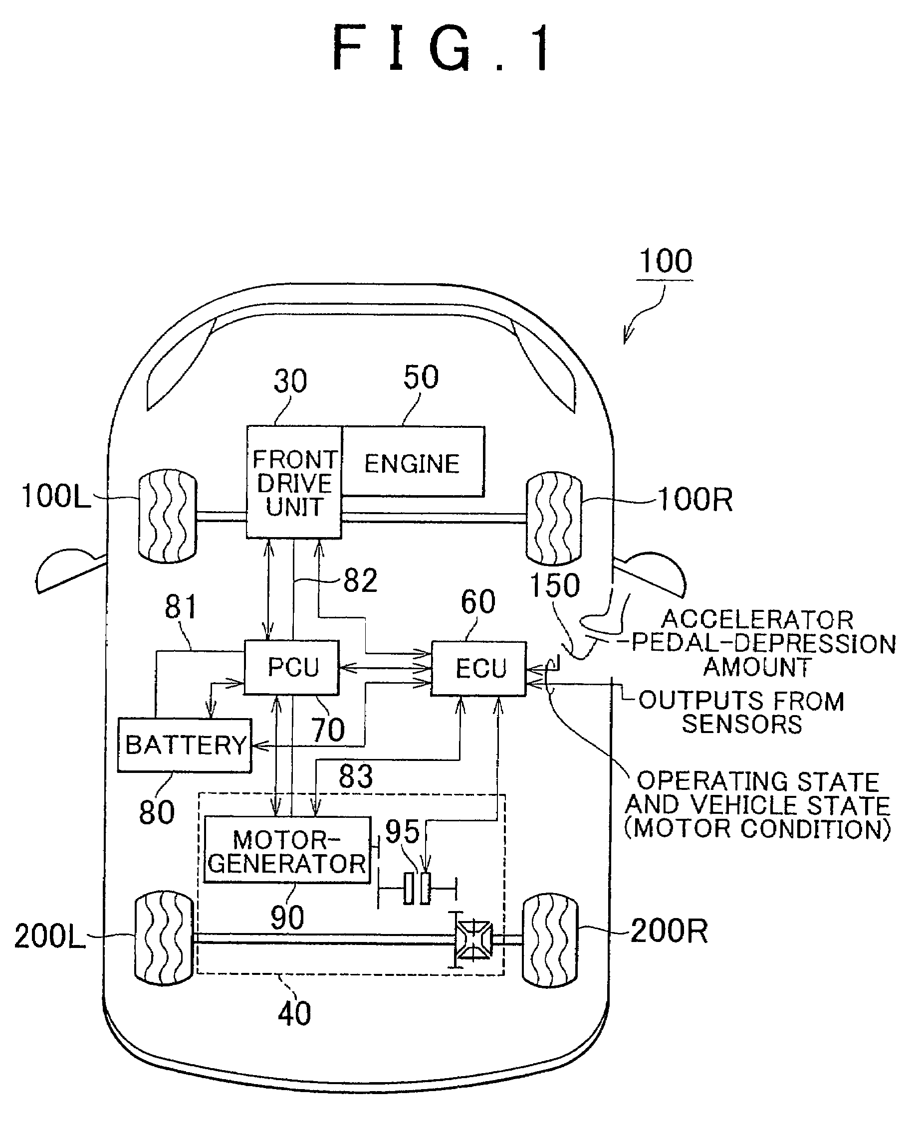
[0027]FIG. 1 shows a block diagram of the configuration of a vehicle that includes the drive apparatus for an electric vehicle according to the embodiment of the invention.

[0028]As shown in FIG. 1, a vehicle 100 according to the embodiment includes front wheels 100L and 100R; rear wheels 200L and 200R; a front drive unit 30 that drives the front wheels; a rear drive unit 40 that drives the rear wheels; an engine 50; an electronic control unit (hereinafter, referred to as “ECU”) 60, a power control unit (hereinafter, referred to as “PCU”) 70; and a battery 80.

[0029]The rear drive unit 40 includes a rear motor-generator 90 and a clutch 95. When the rear motor-generator 90 drives the rear wheels 200L and 200R, it functions as a m...


PUM


Abstract

A drive apparatus for an electric vehicle includes a rotating electric device; a power source; and a terminal block. The rotating electric device drives the wheels of the vehicle. Electric power is supplied to the rotating electric device from the power source through a power-supply passage connected to the rotating electric device through the terminal block, which is fitted to the rotating electric device. The rotating electric device also includes a housing; a stator provided within the housing; and a coil-end positioned at the end of the stator in the axial direction. The terminal block is disposed near the coil-end at a position equal to or lower than the top surface of the housing. The terminal block is fitted to the rotating electric device so that the terminal block is electrically connected to the coil-end, by inserting the terminal block from the side surface of the housing.

Description

[0001]This is a 371 national phase application of PCT / IB2005 / 003910 filed 30 Dec. 2005, claiming priority to Japanese Patent Application No. 2005-018331 filed 26 Jan. 2005, the contents of which are incorporated herein by reference.BACKGROUND OF THE INVENTION[0002]1. Field of the Invention[0003]The invention relates to a drive apparatus for an electric vehicle. More particularly, the invention relates to a drive apparatus for an electric vehicle, which drives an axle using a rotating electric device.[0004]2. Description of the Related Art[0005]Rotating electric devices generally include a stator, a rotor and a contact terminal to which a power-supply cable is connected. Electric power from an external power source is supplied to the rotating electric device through the power-supply cable. Japanese Utility Model Application Publication No. 5-95161 describes a motor (rotating electric device) where a terminal block is provided on the outer periphery of a stator-core.[0006]Compact rota...

Claims


Application Information

Patent Timeline
Patent Type & Authority Patents(United States)
IPC IPC(8): H02K11/00
CPCH02K5/225Y02T10/641Y02T10/64
Inventor IDESHIO, YUKIHIKO
Owner TOYOTA JIDOSHA KK
Why Eureka
Try Eureka