Vehicular image processing apparatus and related method

a technology of image processing apparatus and related methods, which is applied in the field of vehicle image processing apparatus, can solve the problems of deterioration of quality, decrease in detection reliability, and difficulty in adapting the related art structure to suit the vehicle, and achieves high quality and high reliability

Active Publication Date: 2007-01-30
NISSAN MOTOR CO LTD
View PDF10 Cites 58 Cited by
  • Summary
  • Abstract
  • Description
  • Claims
  • Application Information

AI Technical Summary

Benefits of technology

[0007]It is therefore an object of the present invention to provide a vehicular image processing apparatus which provides an image in a high quality and a detection result in a high reliability.

Problems solved by technology

However, with the related art structure, since the images are alternately transmitted for each line, the image is caused to have a deteriorated quality, with a resultant decrease in a reliability in the detection result and, as a result, it becomes hard for the related art structure to be adapted to suit the vehicle.
Further, because of utilizing a high frequency signal, the image processing apparatus is apt to be adversely affected with noises, resulting in deterioration in the reliability of the apparatus.

Method used


Image

  • Vehicular image processing apparatus and related method
  • Vehicular image processing apparatus and related method
  • Vehicular image processing apparatus and related method

Examples


first embodiment

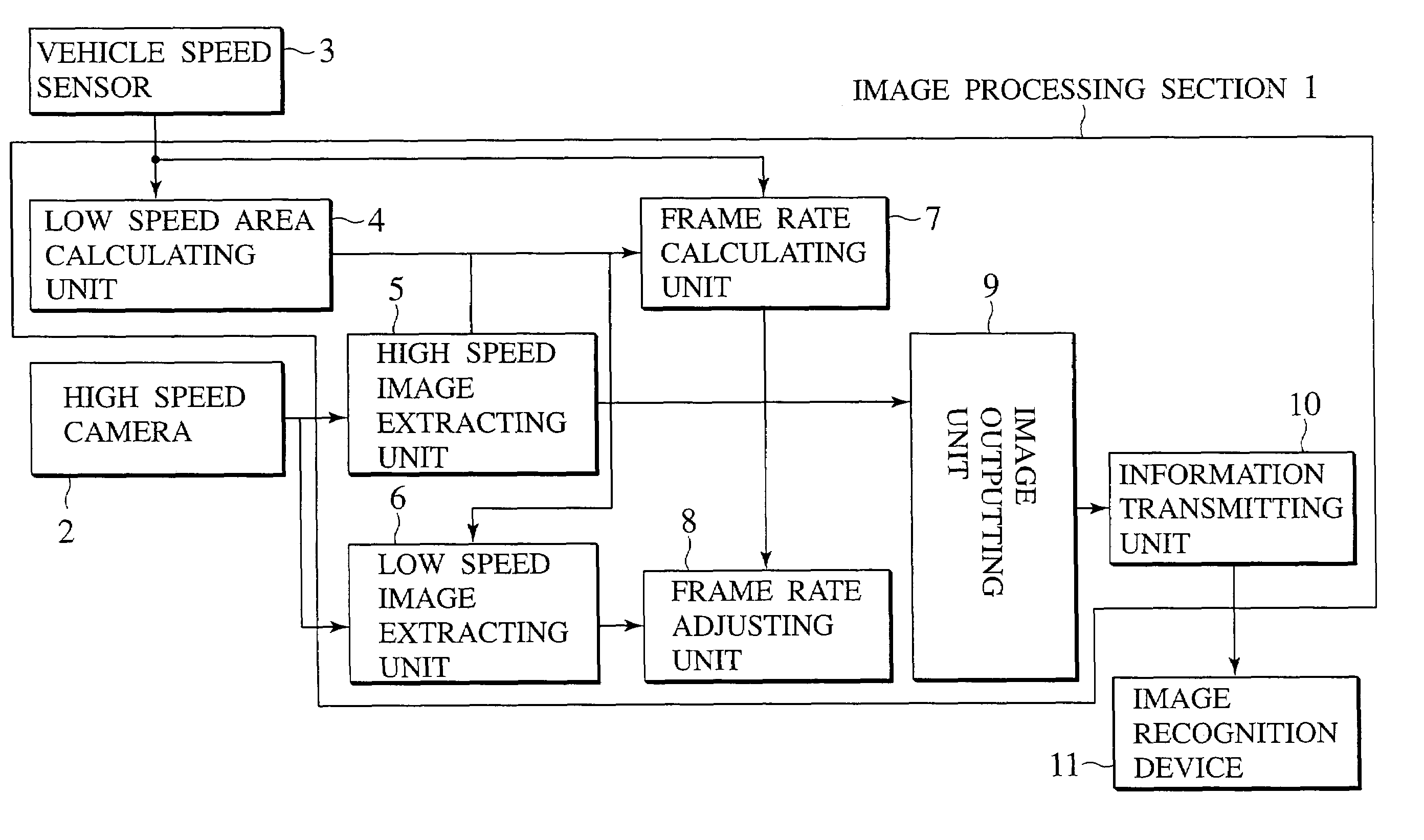
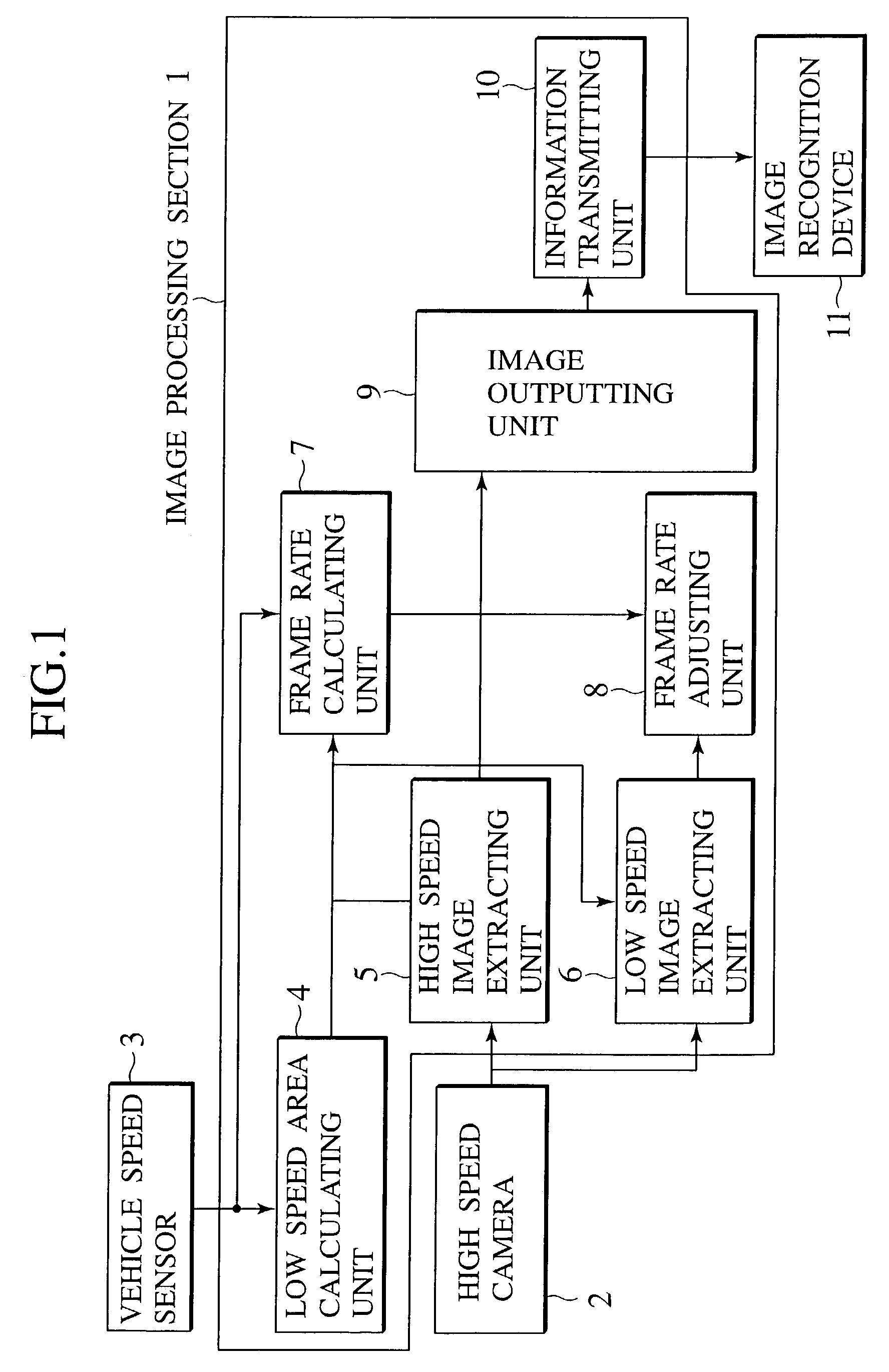
[0015]FIG. 1 is a block diagram illustrating a vehicular image processing apparatus of a first embodiment according to the present invention.

[0016]The image processing apparatus includes an image processing section 1, a high speed camera (electronic type camera) 2, a vehicle speed sensor 3, a low speed area calculating unit 4, a high speed image extracting unit 5, a low speed image extracting unit 6, a frame rate calculating unit 7, a frame rate adjusting unit 8, an image output unit 9, an information transmitting unit 10 and an image recognition device 11.

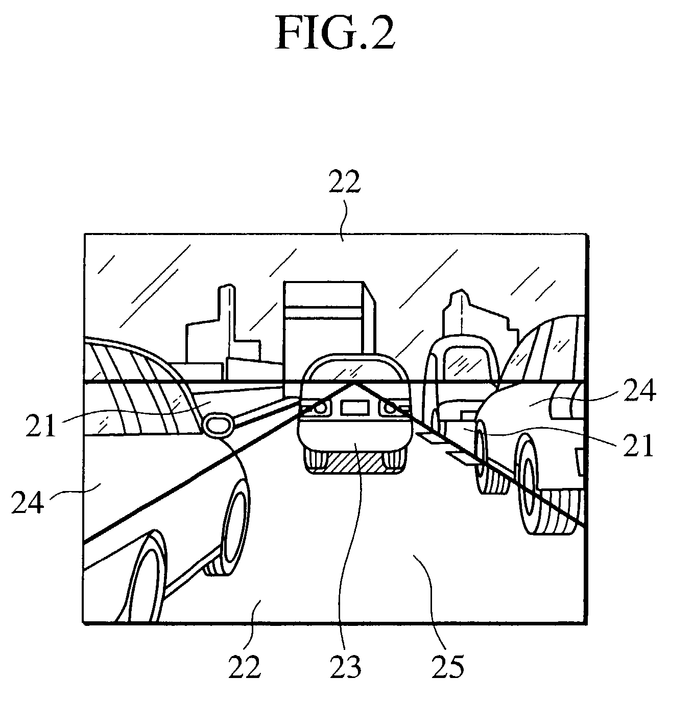
[0017]FIG. 2 is a view of a display screen illustrating an example in which a display area is divided in a high frame rate and a low frame rate with the vehicular image processing of the presently filed embodiment.

[0018]The display screen is shown including a high frame rate area 21, a low frame rate area 22, a preceding vehicle 23, a squeezing vehicle 24 and an own vehicle lane 25.

[0019]The high speed camera 2 is mounted on a veh...

second embodiment

[0052]FIG. 3 is a block diagram illustrating a structure of a vehicular image processing apparatus of a second embodiment according to the present invention.

[0053]The image processing apparatus includes the image processing section 1, the high speed camera 2 (electronic type camera), a low speed camera 12, the vehicle speed sensor 3, the low speed area calculating unit 4, the high speed image extracting unit 5, the low speed image extracting unit 6, the frame rate calculating unit 7, the image output unit 9, the information transmitting unit 10 and the image recognition device 11.

[0054]Here, the second embodiment is described in conjunction with features different from those of the first embodiment set forth above.

[0055]Since the second embodiment is provided with two cameras, i.e., the high speed camera 2, that picks up images at the high frame rate, and a low speed camera 12 that picks up images at the low frame rate, the low speed camera 12 outputs images at the low frame rate an...


PUM


Abstract

A vehicular image processing apparatus and related method are disclosed as having a high speed camera 2 that picks up an image of a surrounding of a vehicle, a low speed image extracting unit 6 extracting an image calculated with a low speed area calculating unit 4, a high speed image extracting unit 5 extracting other image than that calculated with the low speed area calculating unit 4, and an image outputting unit 9 synthesizing image information extracted with the high image extracting unit 5 and image information related to the image of the low speed area to provide an output which is applied to an image recognition device 11 to detect an obstacle around the vehicle or a road shape. A frame rate adjusting unit 8 enables the output image of the low speed image extracting unit 6 to be applied to the image outputting unit 9.

Description

BACKGROUND OF THE INVENTION[0001]The present invention relates to a vehicular image processing apparatus adapted to detect an obstacle of a surrounding of a vehicle or a shape of a road on which the vehicle travels.[0002]An image processing apparatuses proposed in related art is disclosed in Japanese Patent Application Laid-Open No. 2000-253401.[0003]Such an image processing apparatus, that is a device for transmitting digital image data in a full frame, alternately transmits line data in an odd number at one frame and line data in an even number at a subsequent frame, respectively, to allow the volume of transmitting data per unit time to be reduced in half of the volume in which image data in the full frame is transmitted, with an associated receiver being arranged to have a frame composed of line data in the odd number (the even number) and line data in the even number (the odd number) precedingly received to provide an image for thereby reducing the volume of data to be transmit...

Claims


Application Information

Patent Timeline
Patent Type & Authority Patents(United States)
IPC IPC(8): G06K9/00G06T1/00G06T3/00G08G1/16H04N7/18
CPCG06T1/00G06K9/00805H04N7/181G08G1/16G08G1/166G08G1/167G06V20/58
Inventor SATOH, HIROSHI
Owner NISSAN MOTOR CO LTD
Why Eureka
Try Eureka