Apparatus and method for correcting motion of image

a technology of image correction and apparatus, applied in the field of image processing system, can solve the problems of hand shake or vibration of the system, conventional video camera does not consider the correlation between frames, conventional video camera has a limitation in collecting a large volume of images, such as motion pictures, and achieve the effect of increasing the efficiency of compressing an image signal

Inactive Publication Date: 2007-01-30
SAMSUNG ELECTRONICS CO LTD
View PDF7 Cites 46 Cited by
  • Summary
  • Abstract
  • Description
  • Claims
  • Application Information

AI Technical Summary

Benefits of technology

The technical effect of this patent is to improve the quality of images by reducing blurring caused by movement (either from hands or systems). This improves the efficiency of compressing these images in image processing systems that estimate and reduce motion.

Problems solved by technology

The technical problem addressed by this patent is how to improve image processing systems like video cameras by correcting motions caused by shaking hands or vibrating systems, while also optimizing compression efficiency for the collected image data. Conventional video cameras use only one type of compression method, but this limits their ability to efficiently handle larger volumes of footage.

Method used


Image

  • Apparatus and method for correcting motion of image
  • Apparatus and method for correcting motion of image
  • Apparatus and method for correcting motion of image

Examples


Embodiment Construction

[0025]Hereinafter, preferred embodiments of the present invention will be described in detail with reference to the attached drawings.

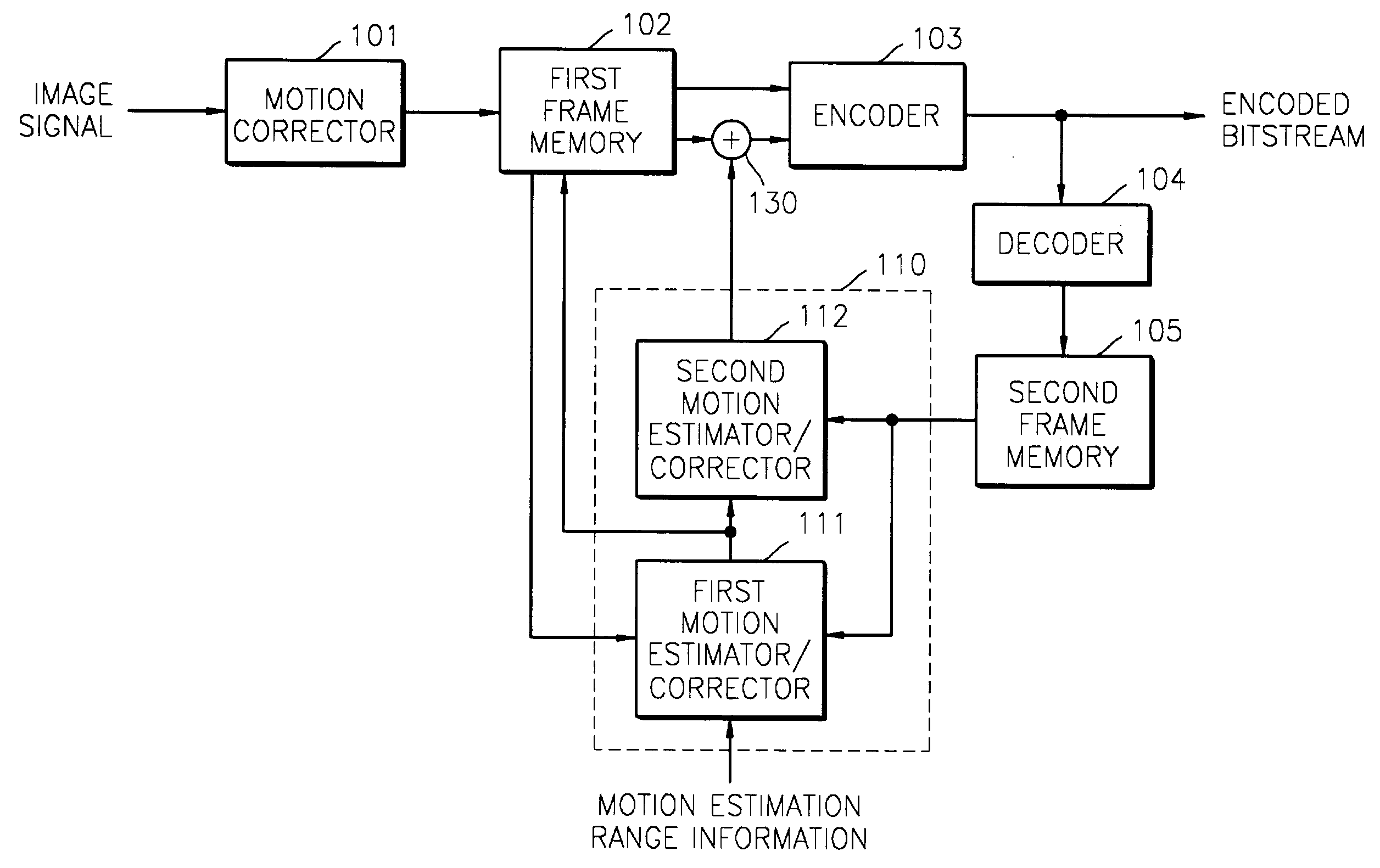
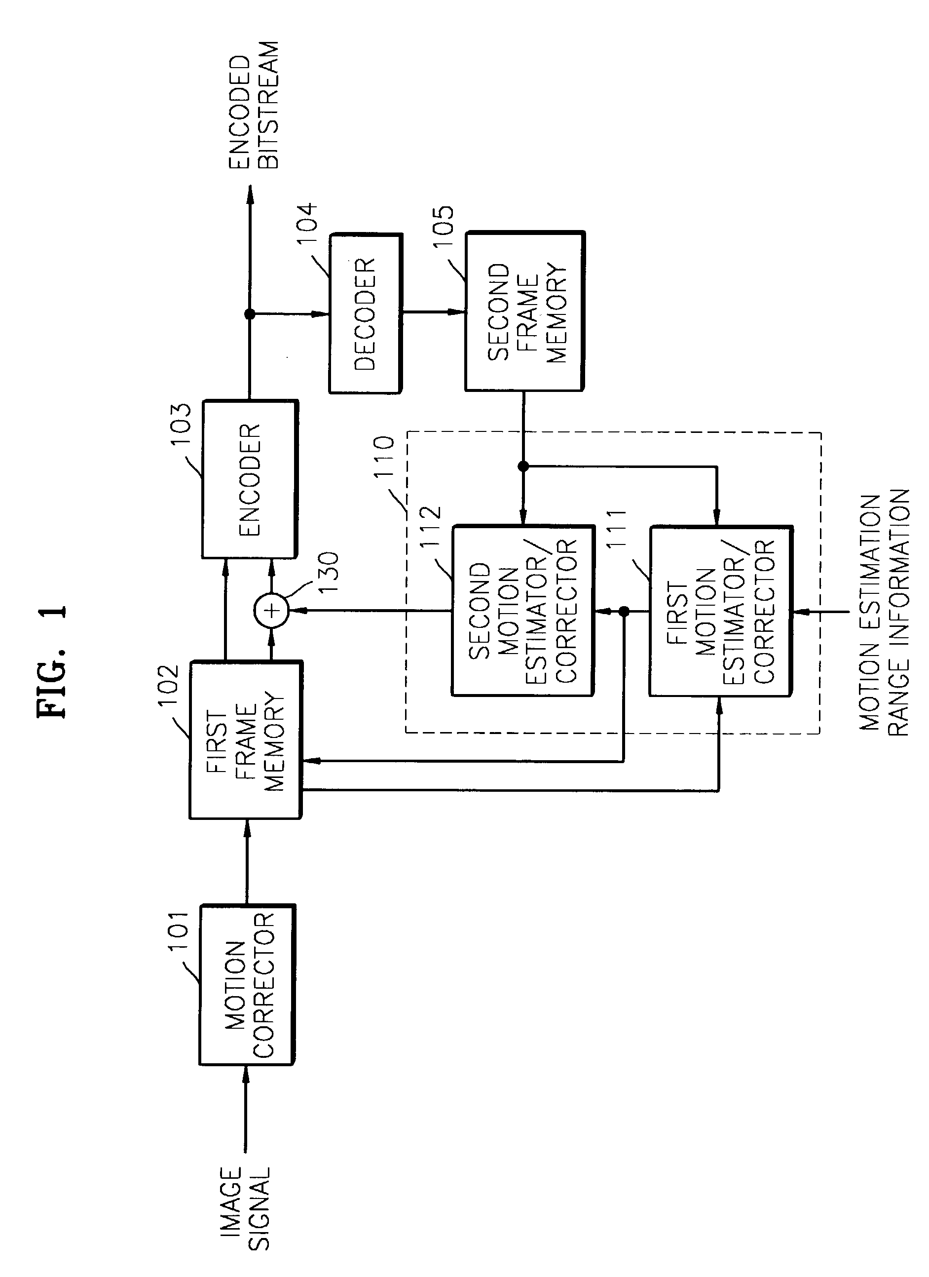
[0026]FIG. 1 is a block diagram of an image processing system having an apparatus for correcting a motion of an image according to a preferred embodiment of the present invention. Referring to FIG. 1, the image processing system includes a motion corrector 101, a first frame memory 102, an encoder 103, a decoder 104, a second frame memory 105, a motion estimation / correction unit 110, and an adder 130.

[0027]The motion corrector 101 corrects a motion included in an input image signal in units of scenes according to a shake of a hand or vibration of a system. As is used in conventional video cameras, a correction method of moving an image on a lens up, down, to the left, or to the right according to the detected amount of vibration may be applied to the motion corrector 101. Besides, any conventional technique of correcting a motion through mechanical or...


PUM


Abstract

An apparatus and method for correcting motion of an image, which occurs due to a shake of a hand or vibration of a system, considering the correlation between frames are provided for an image processing system, which performs motion estimation and compression on an input image signal, thereby increasing compression efficiency. The apparatus includes at least a frame memory and a motion estimator/corrector. The memory stores an input image signal as a current frame image. The motion estimator/corrector estimates a motion of an image within a predetermined motion estimation range in the current frame image on the basis of a previous frame image, detects an image area to be compressed from the current frame image, and provides the detected image area to be compressed as a current frame image area for normal motion estimation so that the motion of the input image signal can be corrected.

Description


Claims


Application Information

Patent Timeline
Owner SAMSUNG ELECTRONICS CO LTD
Why Eureka
Try Eureka