Automatic antenna selection for mesh backhaul network nodes

a backhaul network and automatic antenna selection technology, applied in the field of wireless backhaul networks, can solve the problems of large burden on the backhaul network feeding the area serviced by the localized wireless nodes, and the network is backhaul data transmission

Active Publication Date: 2007-01-30
TELEFON AB LM ERICSSON (PUBL)
View PDF13 Cites 122 Cited by
  • Summary
  • Abstract
  • Description
  • Claims
  • Application Information

AI Technical Summary

Problems solved by technology

One major problem facing wireless networks is backhaul data transmission.
As cellular and PCS voice utilization inside buildings increases and as the data transfer rate provided to the end user increases, the backhaul network feeding the localized wireless nodes gets heavily burdened.
Further, as wireless data speed requirements increase, cell sizes—the area serviced by the localized wireless nodes—must shrink.
Because of the above, high speed, high capacity wireless networks have generally been limited by backhaul bandwidth.
Such bandwidth, previously provided by copper, optical or microwave radio links, comes at a very great cost to the operator and deployer of the wireless network.
In particular, a wired backhaul is expensive to deploy as physical connections must be run to each node.
One problem with wireless backhaul networks is the need for point to point links between the backhaul nodes in the backhaul network.
Installing such backhaul nodes requires extensive set up costs in terms of time and labor as the installation team has to manually point, configure, and setup each backhaul node.
Another issue with some backhaul wireless networks is their limitation to a two dimensional plane.
The approach usually requires more nodes deployed and increased overhead and increased probabilities of problems.

Method used


Image

  • Automatic antenna selection for mesh backhaul network nodes
  • Automatic antenna selection for mesh backhaul network nodes
  • Automatic antenna selection for mesh backhaul network nodes

Examples


Embodiment Construction

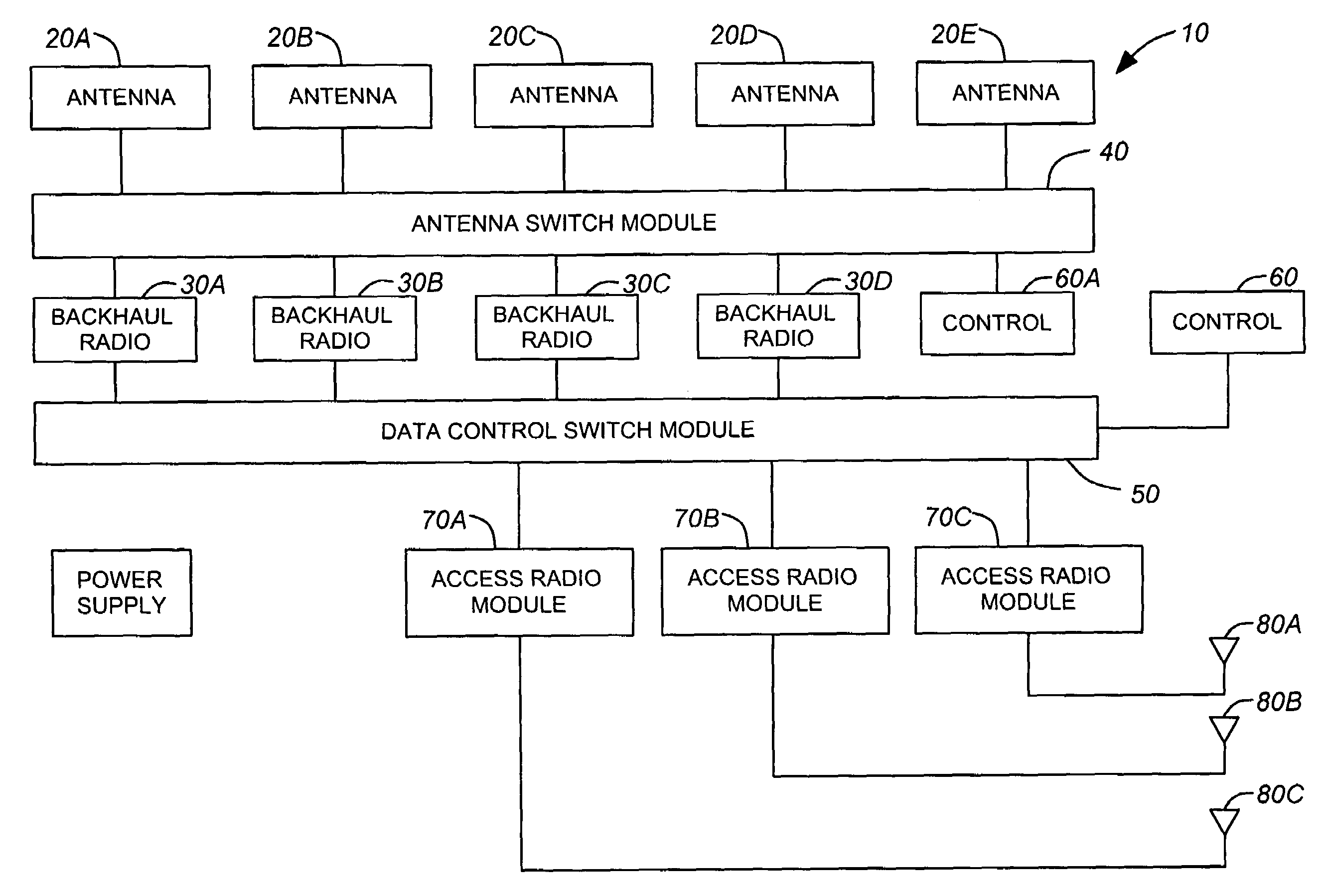
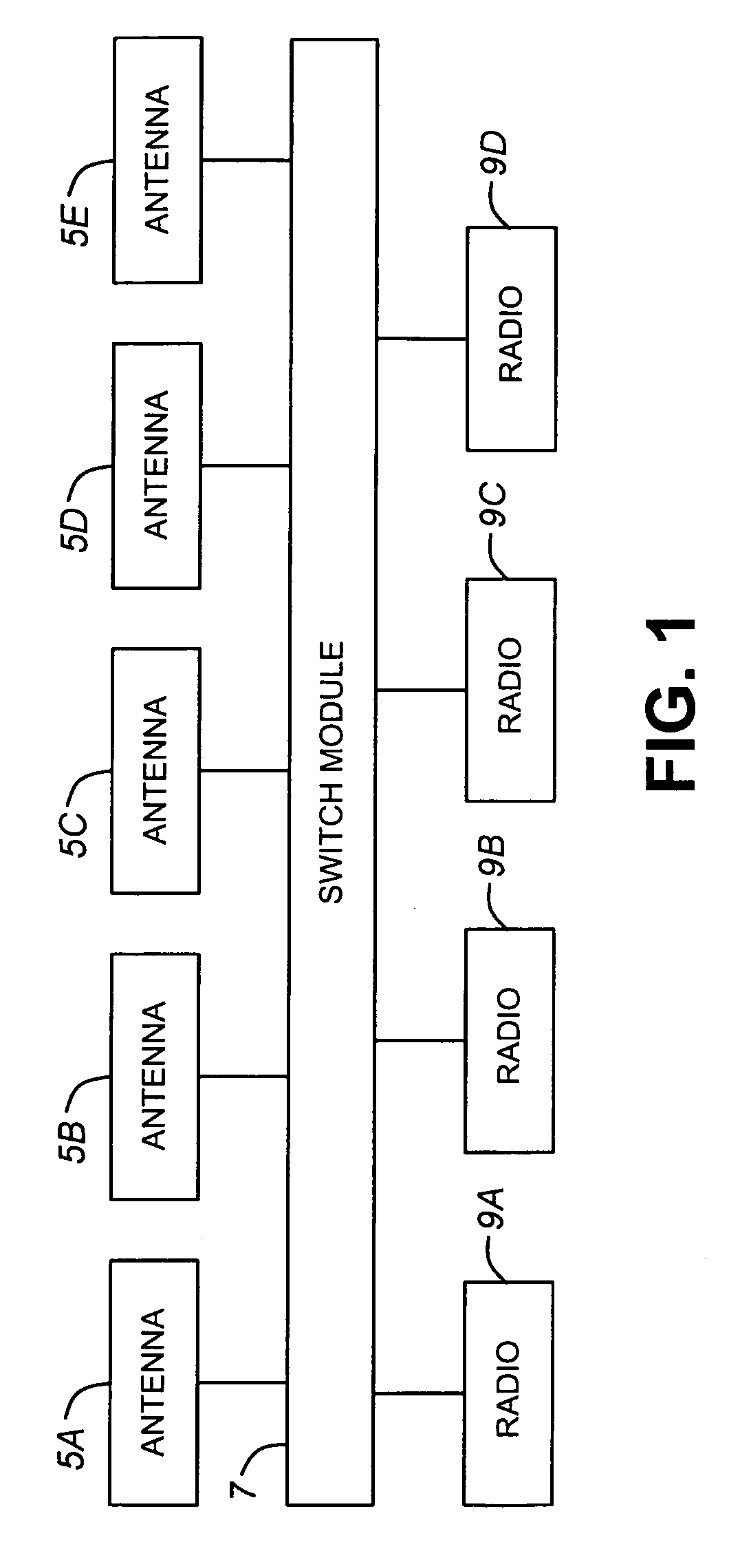
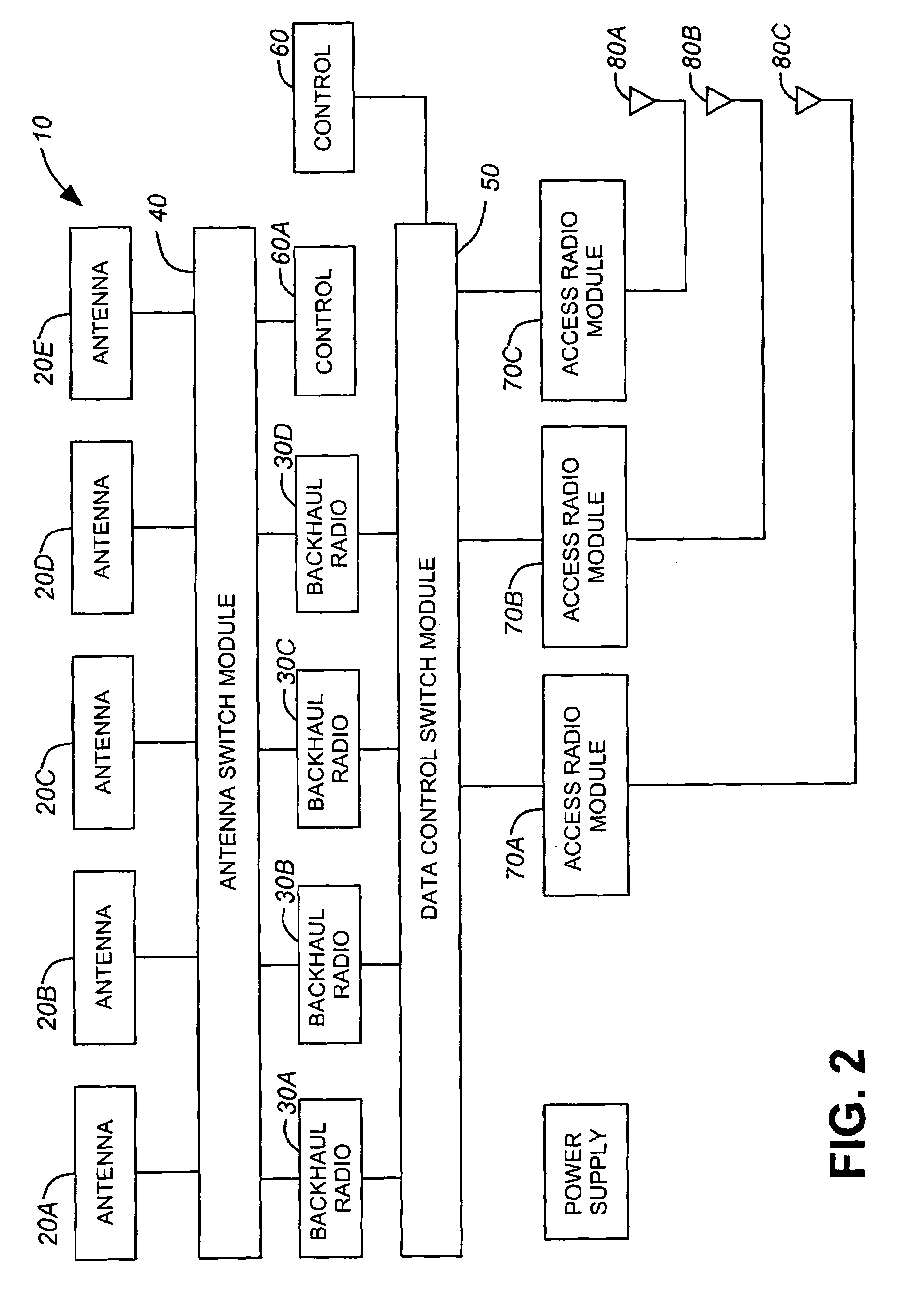
[0051]Referring to FIG. 1, a subsystem which may be used for a wireless communications device is illustrated. The subsystem consists of multiple antennas 5A–5E coupled to a switch module 7 which is, in turn, coupled to multiple radios 9A–9D. The switch module 7 allows any of the radios 9A–9D to use any of the antennas 5A–5E for transmitting signals, receiving signals, or both. The switch module may be a crossbar switch or any suitable switching system that allows radios to be coupled to antennas and vice versa. This subsystem allows the radios 9A–9D to select an antenna from the available antennas which is most suited for a particular task.

[0052]It should be noted that the antennas 5A–5E need not be of the same type or have the same function. These antennas may be polarization diversity antennas, spatial diversity antennas, directional antennas or any other type of antenna. Similarly, the radios 9A–9D need not be of the same type or function. For systems with different types of ante...


PUM


Abstract

Methods and devices related to wireless networking. A wireless device has multiple directional antennas and multiple backhaul radio modules which provide point to point wireless links with other wireless devices. Each radio module can use any one of the available directional antennas to link to one other routing device. Antennas are automatically selected for each wireless device by merely setting one device in a “hunt” mode and setting another device in a “listen” mode. Devices in a hunt mode cycle through the available antennas by sequentially transmitting transmit messages to devices in the listen mode using each of the available antennas in turn. Devices in the listen mode also cycle through their available antennas by sequentially “listening” for transmit messages. A listen mode device, receives transmit messages on each of its available antennas, and, after gathering the relevant data, determines which of its antennas is best suited for communicating with the hunt mode device. The listen mode device antenna which is best suited is then used to transmit a response message to the hunt mode device. This listen mode device antenna is thus configured for communicating with the hunt mode device. Similarly, when the hunt mode device receives the response message, it designates its antenna which transmitted the transmit message as being configured for communications with the listen mode device.

Description

FIELD OF THE INVENTION[0001]The present invention relates to wireless communications networks and, more specifically, is applicable but not limited to methods and devices for use in a wireless backhaul network.BACKGROUND OF THE INVENTION[0002]The communications revolution of the past few years has seen an explosion in the number of wireless devices. Cellular telephones, personal digital assistants (PDAs), laptops, and other consumer devices are using wireless technology to provide connectivity to their users. Wireless technology is currently being used to provide voice-based services for cellular and PCS (Personal Communication Services) telephones, with increasing need for into building coverage. PDAs and laptops can now access the Internet and local dedicated intranets, giving end users access to not only email but also to World Wide Web based content. The increased demand for access to more services in more locations imposes higher performance demands on the wireless infrastructu...

Claims


Application Information

Patent Timeline
Patent Type & Authority Patents(United States)
IPC IPC(8): H04B7/00H04B7/06
CPCH04B7/061
Inventor HERSCOVICH, BERNARDRAYMENT, STEPHEN G.SMITH, ROLAND A.
Owner TELEFON AB LM ERICSSON (PUBL)
Why Eureka
Try Eureka