However, it has been found that this technique is not particularly suited for floorboards that are made of wood-
fiber-based material, especially massive wood material or glued laminated wooden material, to form parquet floors.
One reason why this known technique is not suited for this type of products is the large amount of material waste that arises owing to the
machining of the edge portions to form a tongue groove having the necessary depth.
Also this technique results in high costs of aluminum sections and of the considerable
machining that is required.
Moreover, it is difficult to attach the sectional elements along the edges in a cost-efficient manner.
However, the shown geometry does not allow mounting and dismounting without considerable play by downward and upward angling, respectively, since the components do not go clear of each other during these movements if they are manufactured with a close fit (see FIG. 5b).
A tight fit between all surfaces makes rational manufacture and displacement in the locked position impossible.
This type of mechanical lock, however, causes a large amount of material waste owing to the design of the large locking elements.
The system requires considerable elasticity of the lip provided with the hook, and dismounting cannot take place without destroying the joint edges of the boards.
A tight fit makes manufacture difficult and the geometry of the joint causes a large amount of material waste.
This known locking system suffers from several drawbacks.
Not only does it cause a large amount of material waste in manufacture, it is also difficult to produce in an efficient manner if high-quality joints in a high-quality floor are desired.
It is thus not possible to use large disk-shaped
cutting tools to
machine the board from the side edge.
It is true that these joint systems can be made in an efficient manner using large disk-shaped
cutting tools, but they have the serious drawback that dismounting by upward angling would cause so serious damage to the locking system that the boards could not be laid once more by mechanical locking.
This known system is suited for sports floors of plastic material and cannot be manufactured by means of large disk-shaped cutting tools for forming the sharply undercut groove.
Also this known system cannot be dismounted by upward angling without the material having so great elasticity that the upper and lower lips round the undercut groove are greatly deformed while being pulled apart.
This type of joint is therefore not suited for floorboards that are based on wood-
fiber-based material, if high-quality joints are desired.
This technique certainly causes a small amount of material waste but is not at all suitable if a
floating floor is to be provided, with individual floorboards which, without being damaged, are to be mounted and dismounted in a simple manner and which have high-quality joints.
A serious drawback of the mechanical locking system according to DE-A-3041781 is that it is difficult to produce.
Such a production method is not particularly rational and besides causes great tolerance problems if the production method should be used for producing floorboards or other boards of wood material for forming wall panels or parquet floorboards having high-quality joints.
As mentioned above, a drawback of this prior-art mechanical locking system is that the
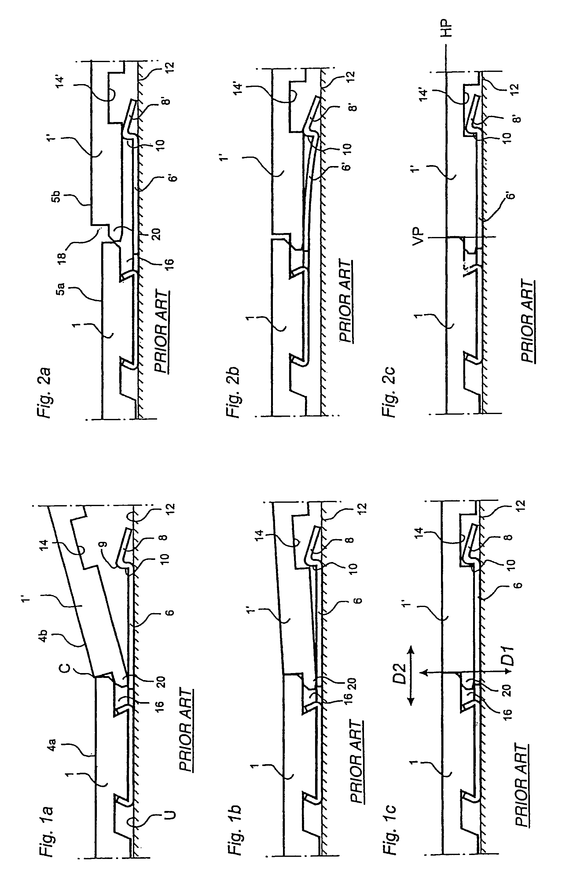
insertion of the angled tongue into the groove requires a considerable amount of play between
tongue and groove (see FIG. 5 in DE-A-3041781 and FIG. 13b in the accompanying drawings) for downward angling to take place, if there is not a considerable degree of elasticity in the board material.
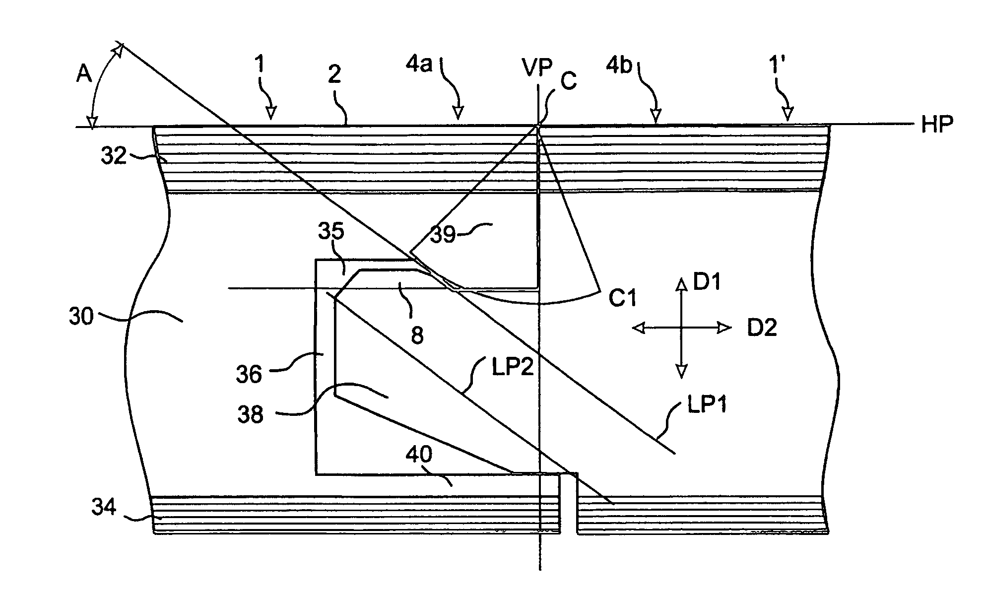
Moreover, such downward angling cannot be carried out while the new board and the previously laid board are brought together in such manner that they touch each other close to the upper edge of the boards above the
tongue and groove respectively, so that the pivoting center of the downward angling motion is positioned at this point.
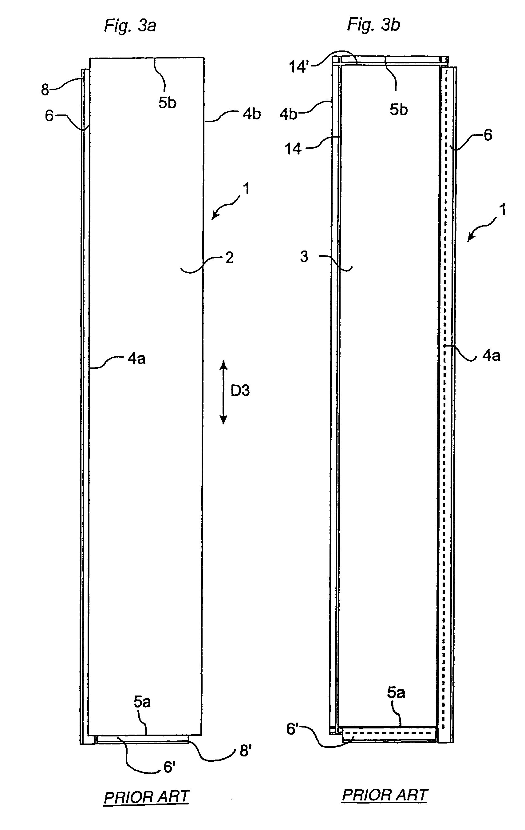
One more drawback of this prior-art mechanical locking system according to DE-A-3041781 in connection with fairly thick boards of wood material is that a displacement of the new board along the previously laid board in the laid or partly raised position is made much more difficult by the boards engaging with each other along large surface portions.
Even if the
machining of wooden boards or boards based on wood
fiber would be carried out very accurately, these surface portions are for natural reasons not quite smooth but have projecting fibers, which significantly increase friction.
In those cases, it will be still more difficult to displace a newly laid board along a previously laid board, if a mechanical locking-together of the boards also at the short sides is desired.
A further drawback of the mechanical locking system according to DE-A-3041781 is that it is not very suited in connection with high-quality floors which are made of wood materials or wood-fiber-based materials and which therefore require a tight fit in the vertical direction between
tongue and groove in order to prevent creaking.
These locking systems also suffer from the drawback that they require a strip portion which extends beyond the joint plane, which causes material waste also within the joint edge portion where the groove is formed.
If this type of joint system would be used for long boards of wood or wood-based material, it would be very difficult to obtain a smooth and simple bringing together.
Moreover, the friction between the arcuate surfaces and between the
tip of the tongue and the bottom of the groove would require considerable forces for displacement of one board along another board in their joined state.
This prior-art technique is certainly better than the one disclosed in the above-mentioned DE-A-3041781, but it suffers from many drawbacks of that technique.
Since tongue and groove are complementarily formed, it is difficult to connect and, optionally, once more pull adjoining floorboards apart.
A deviation from the plane form, i.e. the existence of “banana shape”, results in a further obstacle to the connecting of two such boards.
The risk of damage to the tongue is therefore great, and the design also causes great frictional forces between the surfaces of the tongue and groove.
This short
lower lip, however, has no joining effect since there is a gap between the underside of the tongue and the upper side of this short lip when two boards are joined.
The laid floor will therefore be able to move towards and away from the base, which will cause creaking in the joints and unacceptable vertical displacements.
Owing to the insufficient locking, a high-quality joint cannot be obtained either.
The system suffers from the same drawbacks as these last-mentioned two systems and is not suited for efficient production of floorboards based on wood material or wood fiber material, especially if high-quality joints in a high-quality floor are desired.
However, no locking system is quite suited for rational production of floorboards with a locking system which is optimal as regards production technique, waste of material, laying and taking-up function and which besides can be used for floors which are to have high quality, strength and function in their laid state.

