Kicking shoe attachment for propelling kick scooters and the like

a technology of kicking shoe and propeller, which is applied in the direction of fastenings, heels, footwear, etc., can solve the problems of unsatisfactory power from kicking strokes, constant flexing of stationary legs, and approximately 1:1 height ratio, etc., and achieve good traction

Inactive Publication Date: 2017-12-26
KHURGIN BORIS
View PDF26 Cites 0 Cited by
  • Summary
  • Abstract
  • Description
  • Claims
  • Application Information

AI Technical Summary

Benefits of technology

[0016]Attaching the kicking shoe attachment in accordance with the invention to the shoe of the kicking foot of the rider effectively extends the length of the kicking leg allowing the bottom of the kicking shoe attachment to contact the ground with little or no bending of the rider's stationary leg.
[0017]For casual riding, the height of the kicking shoe attachment is typically designed to be approximately equal to the height of the upper surface of the kick scooter's deck above the ground. However, for a “sporting” style of riding, such an approximately 1:1 ratio of heights may not provide desirable power from the kicking strokes. If the height of the kicking shoe attachment is made lower (i.e., the kicking shoe attachment is made thinner), the rider's center of gravity is shifted toward the kicking foot thereby allowing more powerful kicking strokes.
[0018]A main body core of the kicking shoe attachment is formed from any lightweight sturdy material (e.g., aluminum, plastic, etc.) and may be made in one, two, or more parts. In a two-part body, the parts are arranged one above the other typically with a resilient structure sandwiched between the upper and lower body portions. The resilient structure may include one or more springs or it may be formed from an elastomeric material. The resilient structure between the upper and lower body portions reduce the shock to the kicking leg.
[0021]In a second embodiment, a heel retaining cup is adjustably attached to the substantially flat upper surface by a flat heel cup retainer plate. The heel cup retainer plate may be moved forward and backward along the major axis of the main body. A retaining mechanism is used to secure the position of the heel cup and the heel cup retainer plate along the major axis. Adjustability of the heel retaining cup helps secure the Kicking Shoe Attachment in accordance with the invention more securely to shoes of different sizes and / or styles.
[0025]The bottom surface of the main body is preferably has a convex shape to provide good contact with the ground during the entire duration of the kicking or propelling stroke as the angle of the kicking leg relative to the ground changes. A lower sole also made from rubber or any other suitable durable material is attached to the curved lower surface of the lower body portion. The lower sole provides good traction during the contact with the ground.
[0026]For casual riding, the height of the main body, including upper and lower soles is ideally chosen to be substantially equal to the height of the scooter's platform above the ground. Such a height ensures minimum bending of a rider's stationary leg with each propelling (i.e., kicking) stroke. As previously mentioned, for a “sporting” style of riding, the kicking shoe attachment may be made lower than the height of the kick scooter platform.

Problems solved by technology

The constant flexing of the stationary leg may be very tiring.
However, for a “sporting” style of riding, such an approximately 1:1 ratio of heights may not provide desirable power from the kicking strokes.

Method used


Image

  • Kicking shoe attachment for propelling kick scooters and the like
  • Kicking shoe attachment for propelling kick scooters and the like
  • Kicking shoe attachment for propelling kick scooters and the like

Examples


first embodiment

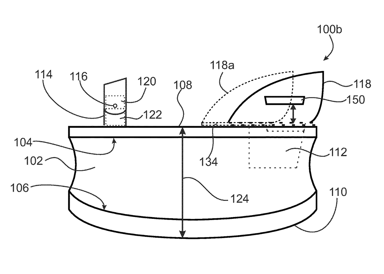
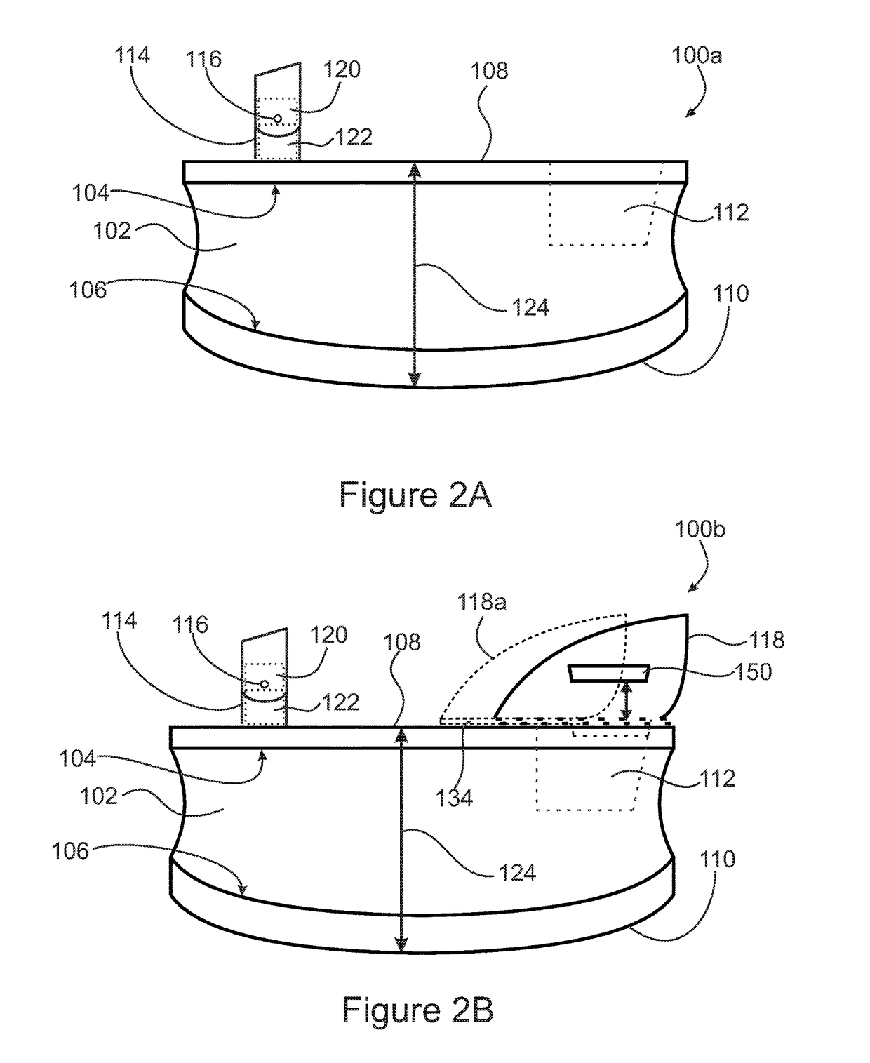
[0052]Referring now also to FIGS. 2A, and 3A there are shown side elevational and top plan schematic views, respectively, of first embodiment of a kicking shoe attachment in accordance with the invention, generally at reference number 100a.

[0053]A solid main body core 102 has a substantially flat upper surface 104, and a convex lower surface 106. In this embodiment, main body core 102 is formed from a solid piece of sturdy, lightweight material. Such lightweight, sturdy materials include lightweight metals such as aluminum and polymers such as ABS. It will be recognized that numerous other lightweight, sturdy materials may be known to those of skill in the art and, consequently, the invention is not limited by the material examples chosen for purposes of disclosure. Rather, the invention is intended to include any suitable main body core 102 material.

[0054]An upper sole 108 is fastened to the upper surface 104 of main body core 102. Upper sole 108 is typically formed from rubber, e...

second embodiment

[0079]Referring now also to FIGS. 4C, 4D and 4E, there are shown a top plan, a first vertical cross-sectional and a second vertical cross-sectional, schematic view, respectively, of a plug, generally at reference number 150b.

[0080]Plug 150b has a substantially flat upper surface 151 with a single finger recess 158 and a pivotable handle 156 disposed therein. Pivotable handle 156 is movable from a flat, stored orientation as shown in FIGS. 4C and 4D. In its flat, stored orientation, pivotable handle 156 lies substantially flush with upper surface 151.

[0081]Pivotable handle 156 may be raised to a vertical, operable orientation as shown in FIG. 4E. When in its vertical, operable orientation, handle 156 may be used to facilitate extraction of plug 150b from substantially circular opening 138138 in heel cup carrier plate 134.

[0082]It will be further recognized that main body core 102 may alternatively be formed by laminated layers. Referring now also to FIG. 5, there is shown a side ele...

third embodiment

[0088]Referring now also to FIG. 7, there is shown a side elevational, schematic view of the kicking shoe attachment with resilient material within the body generally at reference number 200.

[0089]In kicking shoe attachment 200, springs 186 (FIG. 6) are replaced by a block of a resilient material 202. Materials such as polyurethanes, latex, or polyether urethanes (EU) elastomeric foam have been found suitable for the application. It will be recognized by those of skill in that art that suitable other material may be available. Consequently, the invention is not considered limited to the materials chosen for purposes of disclosure. It is anticipated that kicking shoe attachment 200 is less expensive to manufacture while still providing the kicking assist benefits of kicking shoe attachment 180. Resilient material 202 may readily be adhesively attached to a lower surface of upper body portion 182 and an upper surface of lower body portion 184.


PUM


Abstract

A kicking shoe attachment for use by the rider of a kick scooter having an elongated core with a flat upper surface with an upper sole thereupon, and an opposing curvilinear lower surface with a wear resistant lower sole disposed thereupon. Optionally a heel cup connected to a heel cup carrier plate is slidably supported in a heel cup carrier plate receiver. A latching mechanism allows securing the heel cup and carrier plate in a desired position along a major axis of the elongated core. The elongated core may be split apart horizontally and two or more springs, a block of a resilient material or a scissor jack mechanism may be placed between the portions. An opening may be placed in the upper surface of the elongated body to receive the protruding heel of typically a woman's heeled shoe or boot. A removable plug may fill the hole when unneeded.

Description

RELATED APPLICATIONS[0001]This is a Continuation-in-Part application of U.S. application Ser. No. 15 / 140,653 filed Apr. 28, 2016 that is a Continuation-in-Part application of U.S. application Ser. No. 14 / 578,631 filed Dec. 22, 2014 for Kicking Shoe Attachment for Propelling Kick Scooters and the Like, both being included herein in their entirety by reference thereto.FIELD OF THE INVENTION[0002]The invention pertains to footwear attachments and, more particularly, to devices attachable to the sole of a shoe or boot that has a height (i.e., thickness) to allow the “kicking” foot equipped with the device to touch the pavement while requiring little or no bending of the a rider's non-kicking leg standing on the kick scooter.BACKGROUND OF THE INVENTION[0003]Kick scooters are well known and widely used. In addition, so-called skate boards have become widely used in recent years. A rider, particularly of a kick scooter places one of his or her feet on the horizontal wheeled platform of the...

Claims


Application Information

Patent Timeline
Patent Type & Authority Patents(United States)
IPC IPC(8): A43B5/18A43C11/14A43B7/38A43C15/02
CPCA43B5/18A43C15/02A43C11/1493A43B7/38A43B1/0018A43B3/26A43B13/145A43B13/182A43B13/183A43B21/00
Inventor KHURGIN, BORIS
Owner KHURGIN BORIS
Why Eureka
Try Eureka