
Water supply tank unit and heating apparatus having the same

a technology of water supply tank and water supply tank, which is applied in the direction of lighting and heating apparatus, container discharge methods, stoves or ranges, etc., can solve the problems of user misunderstanding that the water supply tank is leaking, limit heat cooking, and small amount of water in the water inl

Active Publication Date: 2007-02-06
PANASONIC CORP
View PDF16 Cites 21 Cited by
  • Summary
  • Abstract
  • Description
  • Claims
  • Application Information

AI Technical Summary

Benefits of technology

[0014]Further, the water supply tank unit of the invention is characterized in that: the tank support member has at its bottom an elastic fitting piece provided with a projection part which fits to the water supply tank inserted to the tank support member and locks the water supply tank; and the elastic fitting piece is formed by providing a cavity around the elastic fitting piece except its base part at the bottom of the tank support member, and the cavity is used as the scupper. Therefore, the water supply tank is held surely in the tank support member by the projection part. Further, since the water that has leaked into the tank support member drops from the cavity around the elastic fitting piece and is absorbed by the water absorption member, labor and cost for forming the scupper newly can be omitted.

Problems solved by technology

However, heating by only use of high-frequency heating, limits heat cooking.
However, in case that the water supply tank is pulled out from the tank support member, when the water supply port of the water supply tank separates from the water inlet on the heating apparatus side, a small amount of water may drop into the water inlet due to pressure of the water supply pipe path.
Therefore, there is fear that this water that has dropped stays in a member for housing the water supply tank on the heating apparatus side and it enters in a circuit area such a power supply into the heating apparatus to influence the circuit area.
Further, when the water that has leaked into the member for housing the water supply tank is attached to the bottom surface of the water supply tank, there is fear that a user misunderstands that the water is leaking from the water supply tank.

Method used


Image

  • Water supply tank unit and heating apparatus having the same
  • Water supply tank unit and heating apparatus having the same
  • Water supply tank unit and heating apparatus having the same

Examples


Embodiment Construction

[0027]One embodiment of water supply tank structure of the invention will be described in detain below with reference to attached drawings.

[0028]Herein, as an example of a heating apparatus having a steam generating function and being provided with a water supply tank unit, a high-frequency heating apparatus with a steam generating function is taken.

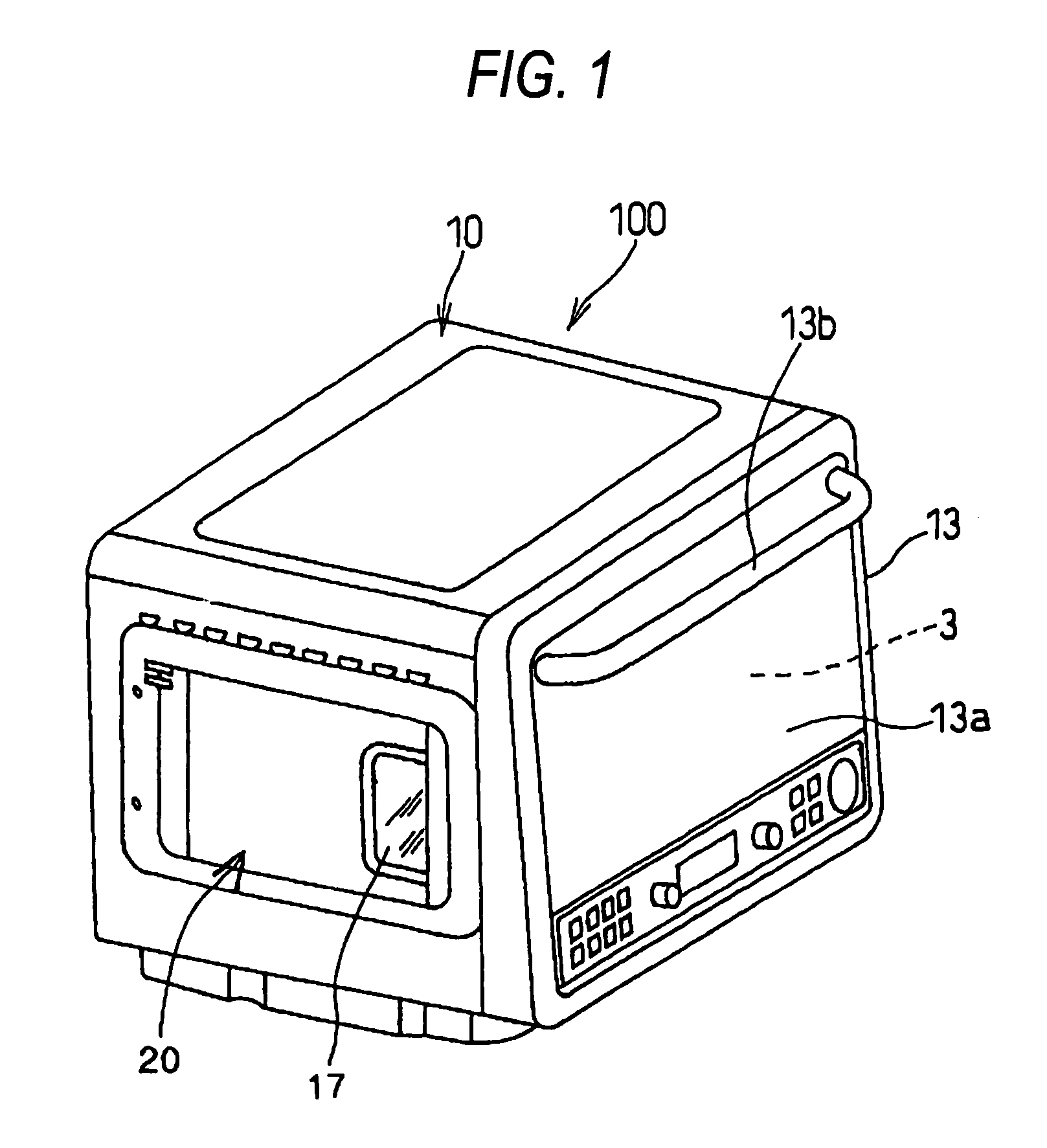
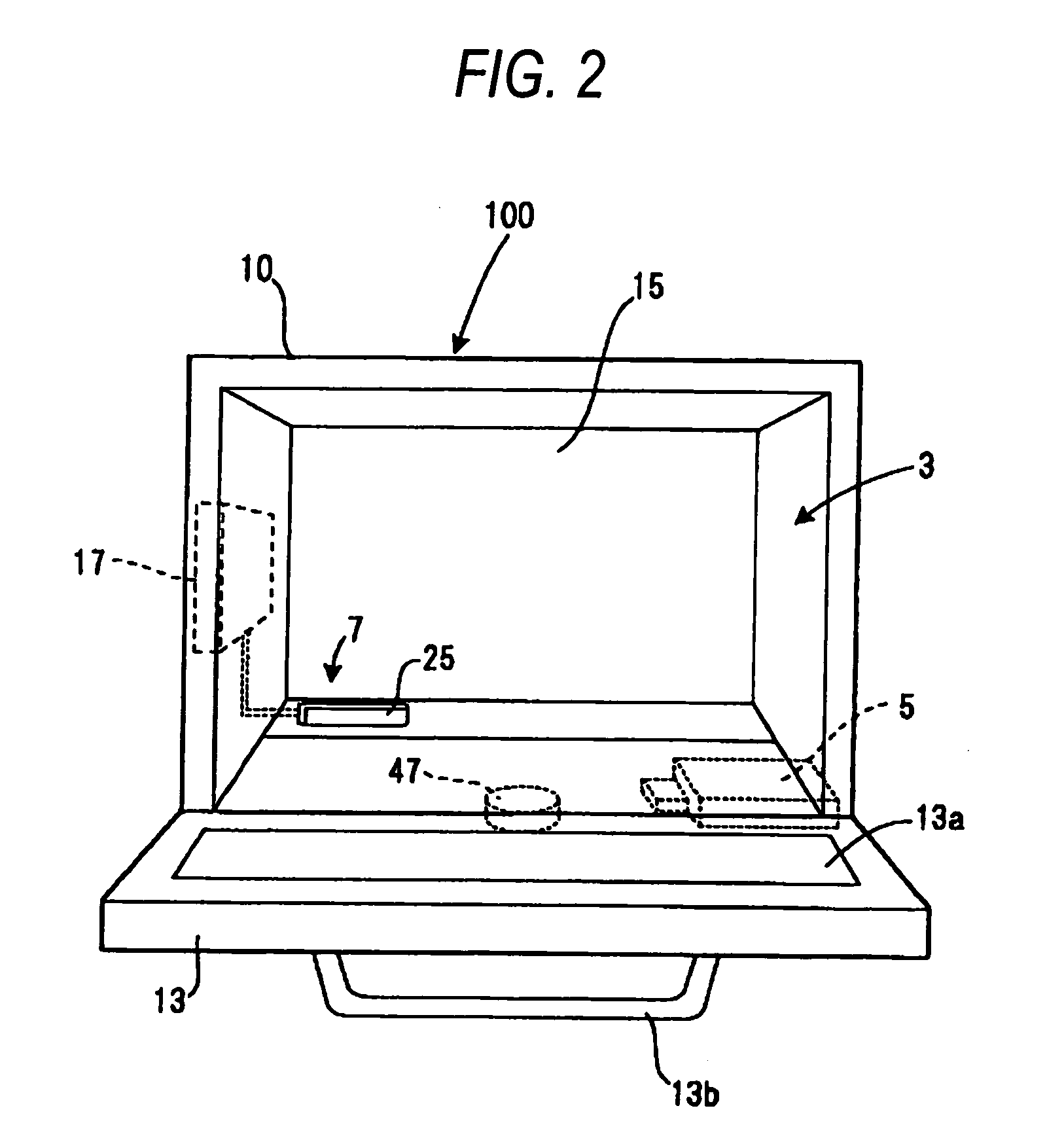
[0029]FIG. 1 is an exterior perspective view of a high-frequency heating apparatus with a steam generating function according to the invention, and FIG. 2 is a schematically front view showing a state where an opening-and-closing door of the high-frequency heating apparatus with a steam generating function is opened.

[0030]In the invention, as shown in FIG. 1, in order to give the steam generating function to a high-frequency heating apparatus 100, a water supply tank unit in which a water supply tank for supplying water to a steam generating part is housed is arranged on a side surface of the high-frequency heating apparatus 100. The inv...


PUM


Abstract

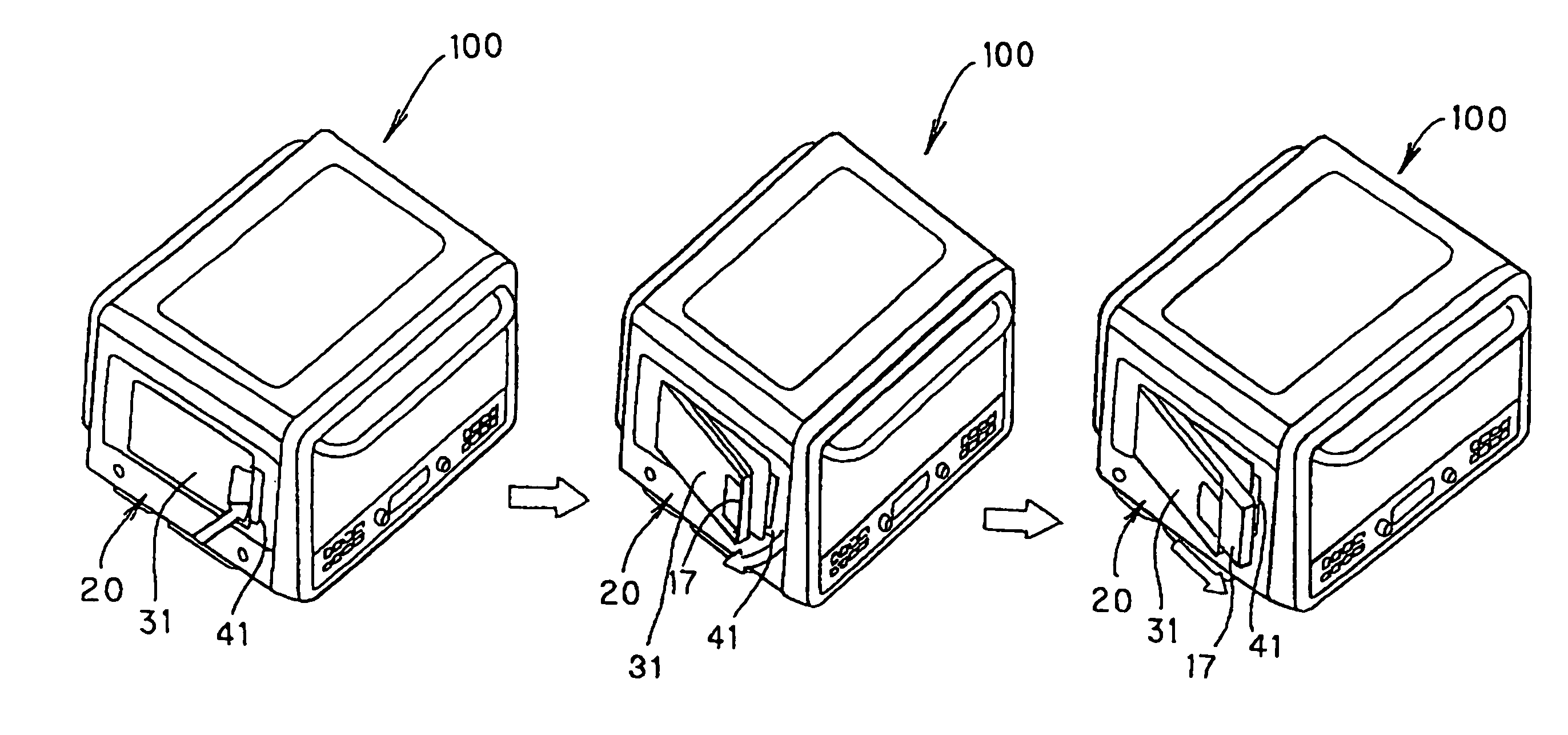
The present invention provides a water supply tank unit which can treat water that has leaked when a water supply tank is pulled out so that it does not remain. In the invention, a water supply tank unit which is attached to a high-frequency heating apparatus with a steam generating function and holds a water supply tank detachably, said tank unit comprises: a water supply tank 17 having a water supply port 55 on its side surface; a tank case door member 31 for supporting the water supply tank 17, which has a water inlet 59 connected to the water supply port 55 with an inserting operation of the water supply tank 17, and a scupper 60 formed around an elastic fitting piece by perforating a bottom part near the water inlet 59; and a sponge provided below the scupper 60.

Description

BACKGROUND OF THE INVENTION[0001]1. Field of the Invention[0002]The present invention relates to a water supply tank unit which is attached to a heating apparatus having a steam generating function and holds a water supply tank detachably. Moreover, the present invention relates to a heating apparatus having the water supply tank unit.[0003]2. Description of the Related Art[0004]A high-frequency heating apparatus provided with a high-frequency generating means which outputs a high frequency wave into a heating room in which a heated matter is housed, since it can efficiently heat the heated matter into the heating room in a short time, has spread rapidly as an electronic oven that is a heat cooking device for food material.[0005]However, heating by only use of high-frequency heating, limits heat cooking.[0006]Therefore, a high-frequency heating apparatus in which an electric heating device that generates heat into a heating room is added to enable oven heating has been proposed, and...

Claims


Application Information

Patent Timeline
IPC IPC(8): F24H1/18F22B1/28A47J27/04F24C1/00F24C7/02H05B6/80
CPCH05B6/6479H05B6/6426A47J27/04Y10S261/65
Inventor HAYAKAWA, YUJIKANZAKI, KOUJIINOUE, YASUHIKOSUGIMOTO, TAKASHIFUKUMURA, KENICHIRO
Owner PANASONIC CORP
Learn More