Thermostat for two-system cooling device

a cooling device and thermostat technology, applied in the direction of machines/engines, process and machine control, instruments, etc., can solve the problems of increasing increasing the fuel consumption ratio, and increasing the complexity of the structure, so as to reduce the size of the entire apparatus, reduce the number of structural components, and accelerate the warm-up of the engine head

Inactive Publication Date: 2007-02-06
NIPPON THERMOSTAT CO LTD
View PDF9 Cites 11 Cited by
  • Summary
  • Abstract
  • Description
  • Claims
  • Application Information

AI Technical Summary

Benefits of technology

[0023]In accordance with the present invention, the improvement of the conventional structure of the thermostat in which a bypass valve provided on the bottom side closes a passage according to the lift of the main valve makes it possible to obtain a configuration in which the second valve body for open-close control of the passage on the cylinder block side closes when the first valve body for open-close control on the cylinder head side is closed, and the second valve body is open according to the prescribed amount of lift of the piston rod when the first valve body side is open. Further, the control of cooling water in the cooling water passages of the two circuits is conducted at respective prescribed timing.
[0029]Further, in accordance with the present invention, fusing rubber or the like, as means for sliding against the tubular sleeve, to the outer peripheral portion of the second valve body improves slidability of the second valve body and sealing properties of the sliding portion. As a result, cooling water control in the second valve body can be carried out even more accurately.

Problems solved by technology

Incidentally, it is well known that in automobile engines, a fuel consumption ratio is increased if mechanical friction of the engine is reduced.
As a result the number of structural components was increased, the structure became complex, the cost was increased and the entire apparatus increased in size.
Therefore, the thermostat structure was complex and the entire apparatus increased in size.
As a result, the structure was complex.
Further, in a thermostat of a bottom bypass type that has been known conventionally, the first and second valves are linked so that only a transition from the open state to the close state is possible and cannot be directly used.

Method used


Image

  • Thermostat for two-system cooling device
  • Thermostat for two-system cooling device
  • Thermostat for two-system cooling device

Examples


Embodiment Construction

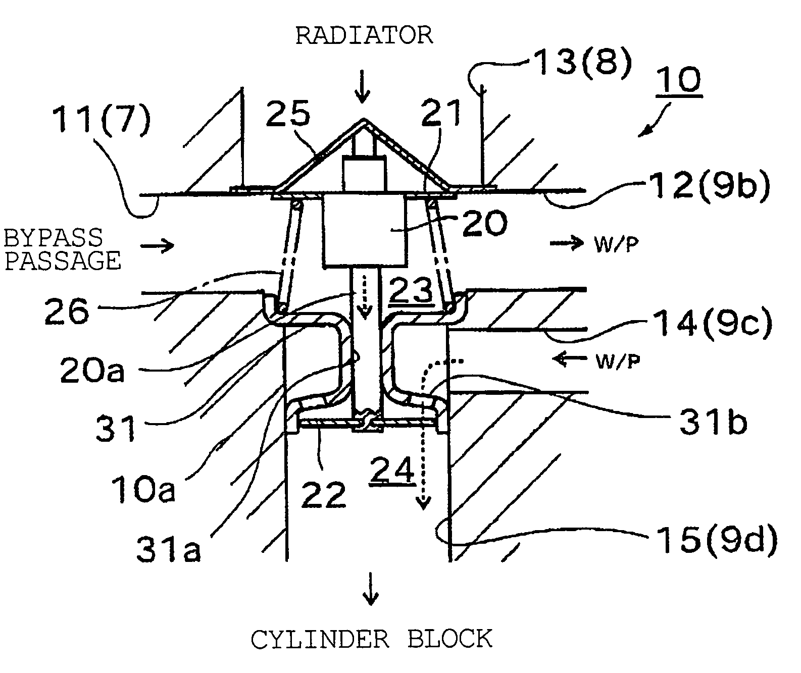
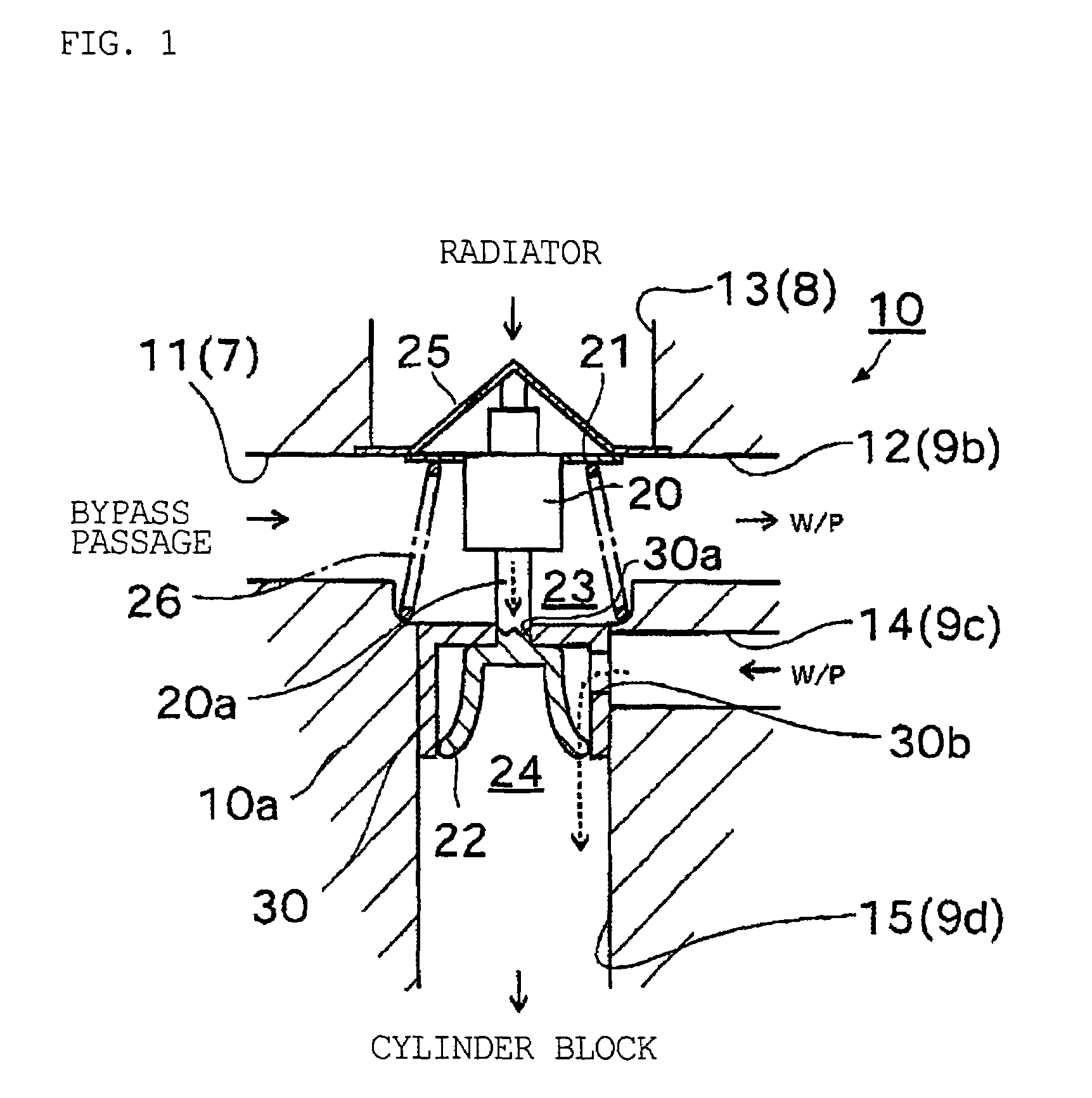
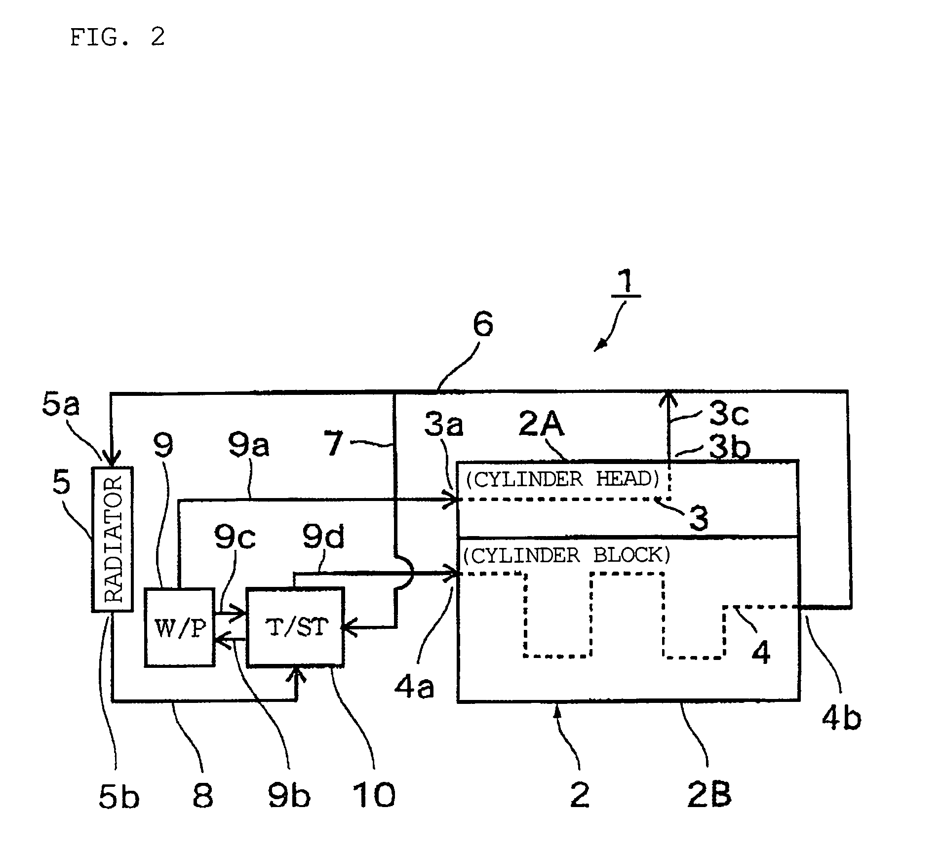
[0034]FIG. 1 and FIG. 2 illustrate an embodiment of the thermostat for a dual-circuit cooling system in accordance with the present invention. Of those figures, first, the main features of a dual-circuit cooling system 1 comprising a thermostat 10 in accordance with the present invention will be explained hereinbelow with reference to FIG. 2.

[0035]In FIG. 2, the reference numeral 2 stands for an automotive engine as an internal combustion engine composed of a cylinder head 2A and a cylinder block 2B. Respective independent cooling water passages 3, 4 are formed in the cylinder head 2A and the cylinder block 2B of the engine 2.

[0036]The reference numeral 5 stands for a heat exchanger, that is, a radiator. A cooling water inlet portion 5a and a cooling water outlet portion 5b of the radiator 5 are connected by a cooling water circuit for circulating the cooling water in the cooling water passages 3, 4 in the cylinder head 2A and cylinder block 2B of the engine 2.

[0037]This cooling wat...


PUM


Abstract

A thermostat independently controlling cooling water passages of two circuits, including a first valve body having first and second passages in constant communication. A third passage is selectively connected to those passages. Communication of the third passage is disconnected when the cooling water temperature is below a prescribed temperature, and the valve is opened when the cooling water temperature is equal to or higher than the prescribed temperature. A second valve body, having fourth and fifth passages selectively in communication, closes the valve to disconnect those passages when the cooling water temperature is below the prescribed temperature, and opens the valve by operating the first valve body to link the passages when the cooling water temperature is equal to or higher than the prescribed temperature. A tubular sleeve prevents first and second control chambers, respectively including the first and second valve bodies, from communicating with each other.

Description

TECHNICAL FIELD[0001]The present invention relates to a thermostat for a cooling system used for conducting flow rate control of cooling water independently in two circuits in a cooling system in which cooling water for cooling an internal combustion engine (referred to hereinbelow as an engine) used in automobiles or the like is circulated between the engine and a heat exchanger (referred to hereinbelow as a radiator).BACKGROUND ART[0002]In automobile engines, a cooling system of a water cooling type employing a radiator is typically used to cool the engine. In the cooling systems of this type, a thermostat using a thermally expandable body for adjusting the amount of cooling water circulating on the radiator side has been conventionally used, so that the temperature of the cooling water introduced into the engine could be controlled.[0003]Thus, a thermostat using the aforesaid thermally expandable body is installed in part of a cooling water passage, for example, on the inlet side...

Claims


Application Information

Patent Timeline
Patent Type & Authority Patents(United States)
IPC IPC(8): G05D23/02F01P7/14F01P7/16F16K31/68G05D23/13
CPCF01P7/16G05D23/134F16K11/02F01P2003/027F01P2037/02F16K31/00
Inventor MASUKO, TAKASHIMORI, AKIRAYOSHIHARA, TORU
Owner NIPPON THERMOSTAT CO LTD
Why Eureka
Try Eureka