Rotational atherectomy system with stationary cutting elements

a rotating atherectomy and stationary cutting technology, applied in the field of medical devices, can solve the problems of limiting affecting the efficiency of the device, so as to achieve the effect of reducing the length of the cavity in the device, reducing the length of the portion excised at each pass of the atherectomy blade, and reducing the utility of the devi

Inactive Publication Date: 2007-02-06
TYCO HEALTHCARE GRP LP
View PDF255 Cites 320 Cited by
  • Summary
  • Abstract
  • Description
  • Claims
  • Application Information

AI Technical Summary

Benefits of technology

[0011]There is provided in accordance with one aspect of the present invention, a rotational medical device. The device comprises an elongate flexible tubular body, having a proximal end and a distal end. A rotatable element extends through the body. A rotatable tip at the distal end of the body is connected to the rotatable element.

Problems solved by technology

If left untreated, such stenoses can so sufficiently reduce perfusion that angina, hypertension, myocardial infarction, strokes and the like may result.
While such devices provide for directional control in selection of tissue to be excised, the length of the portion excised at each pass of the atherectomy blade is necessarily limited to the length of the cavity in the device.
The length and relative rigidity of the housing limits the maneuverability and therefore also limits the utility of the device in narrow and tortuous arteries such as coronary arteries.
Such devices are also generally limited to lateral cutting relative to the longitudinal axis of the device.
However, not all atherosclerotic plaques are hardened, calcified atherosclerotic plaques.
Thus, one cannot always rely entirely on the differential cutting properties of such abrasives to remove atherosclerotic mater

Method used


Image

  • Rotational atherectomy system with stationary cutting elements
  • Rotational atherectomy system with stationary cutting elements
  • Rotational atherectomy system with stationary cutting elements

Examples


Embodiment Construction

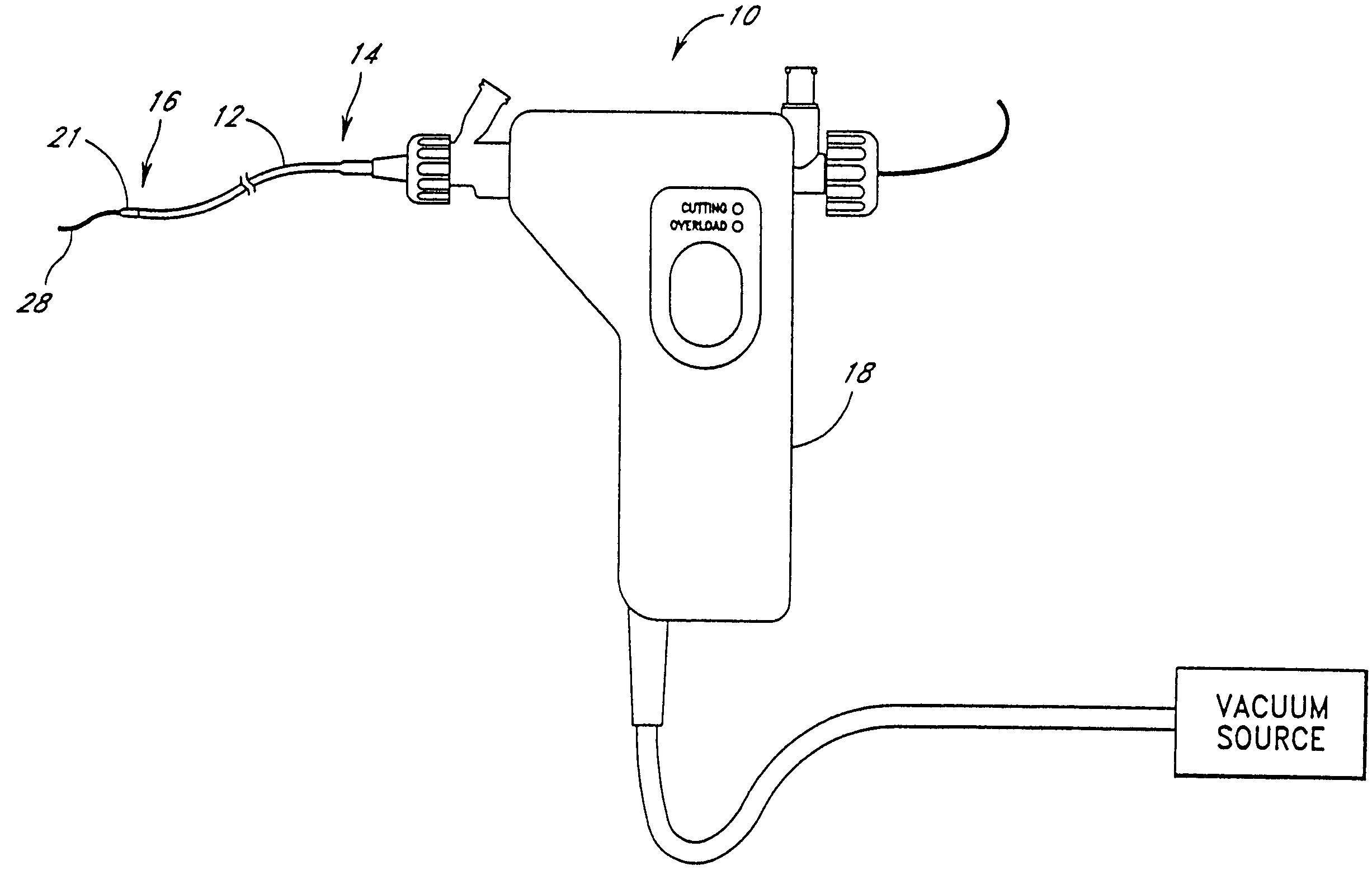
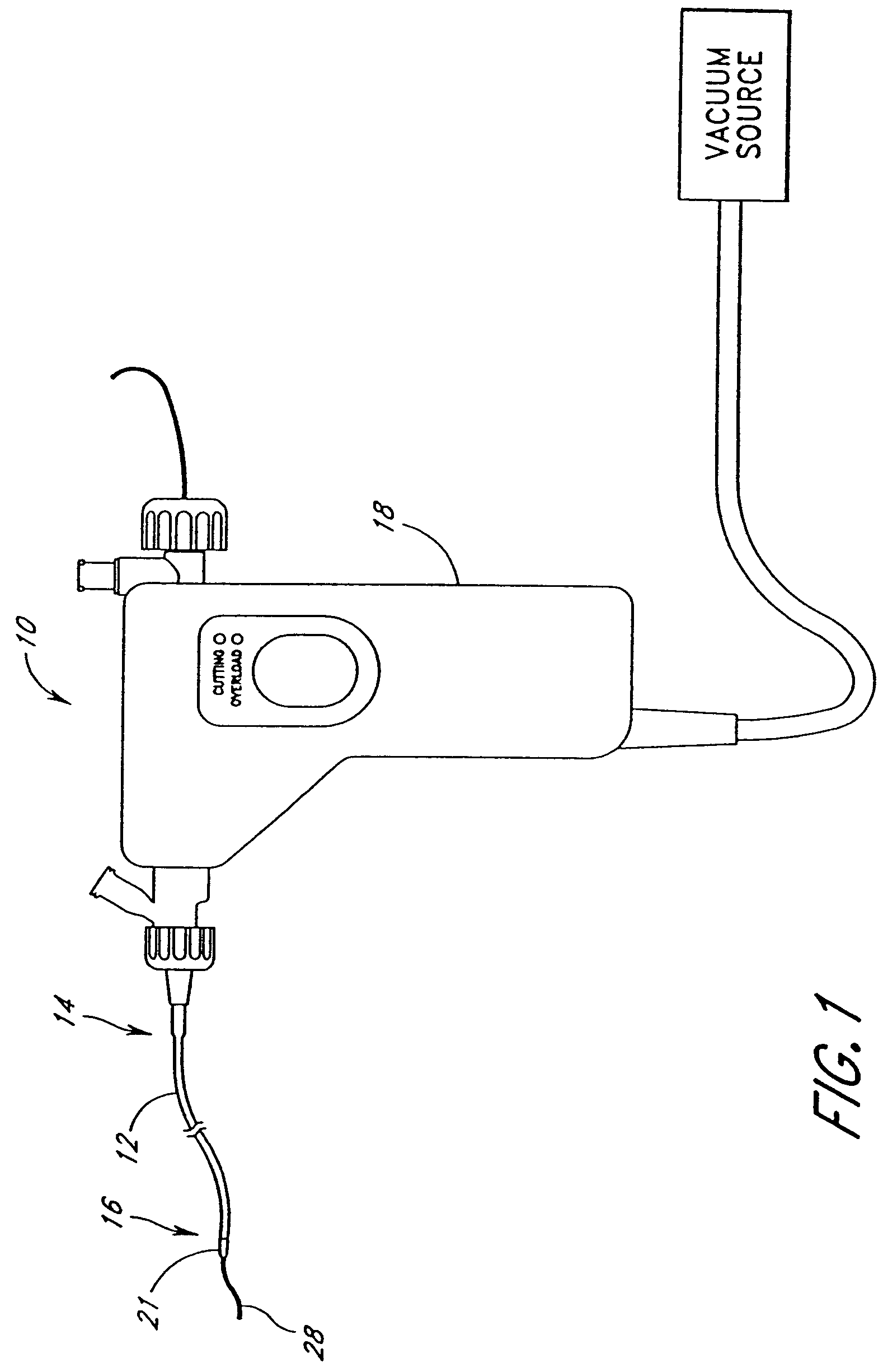
[0037]With reference initially to FIG. 1, a surgical instrument, indicated generally by reference numeral 10 having features, aspects and advantages in accordance with the present invention is depicted therein. In general, the illustrative surgical instrument comprises an elongate flexible tubular body 12 having a proximal end 14 and a distal end 16. A control 18 is preferably provided at or near the proximal end 14 of the tubular body 12 for permitting manipulation of the instrument 10. The control 18 advantageously carries electronic controls and indicators as well as vacuum controls as will be discussed below.

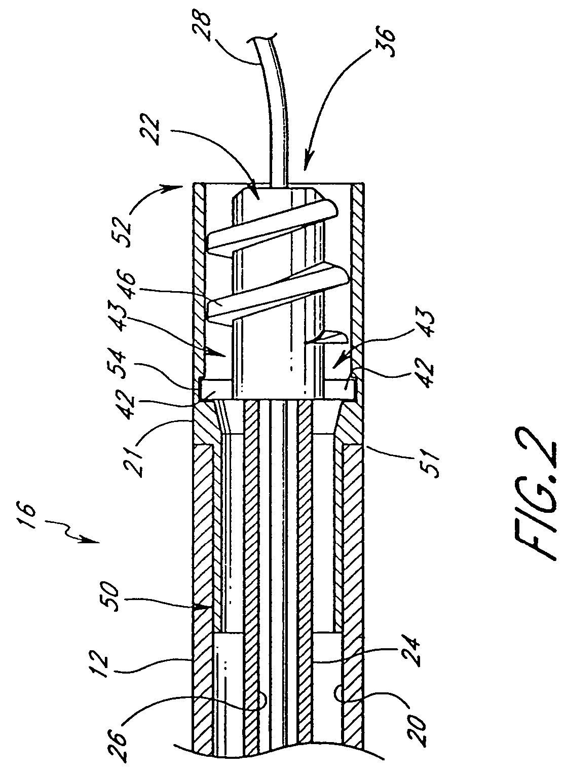
[0038]With reference now to the partially sectioned view of FIG. 2, the tubular body 12 preferably has an elongate central lumen 20. Desirably, the tubular body 12 has a cutter housing 21 for receiving a cutter 22 that may rotate therein. The illustrated cutter 22 is coupled to the control 18 for rotation by way of an elongate flexible drive shaft 24, as will be described be...


PUM


Abstract

An elongate tubular body extends between a rotatable cutter and a control. The cutter is connected to the control with a rotatable element. A vacuum is applied through an annular passage defined between the tubular body and the rotatable element. The cutter has at least one radial projection which cooperates with at least one stationary element on the tubular body to cut material drawn into the tubular body. Material that has been processed by the cutter is aspirated through the tubular body for disposal.

Description

CROSS REFERENCE TO RELATED APPLICATION[0001]This application is a continuation of U.S. patent application Ser. No. 10 / 158,295, filed May 28, 2002 now abandonded; which is a continuation of Ser. No. 09 / 592,218, filed Jun. 12, 2000, now U.S. Pat. No. 6,451,036; which is a continuation of U.S. patent application Ser. No. 09 / 398,241, filed Sep. 17, 1999 now U.S. Pat. No. 6,666,874; which is a continuation-in-part of U.S. patent application Ser. No. 09 / 260,199, filed Mar. 1, 1999, now U.S. Pat. No. 6,206,898; which is a continuation-in-part of U.S. patent application Ser. No. 09 / 058,513, filed Apr. 10, 1998, now U.S. Pat. No. 6,001,112.BACKGROUND OF THE INVENTION[0002]1. Field of the Invention[0003]The present invention generally relates to medical devices and, more particularly, to atherectomy catheter devices.[0004]2. Description of the Related Art[0005]A variety of techniques and instruments have been developed to remove obstructive material in arteries or other body passageways or to...

Claims


Application Information

Patent Timeline
IPC IPC(8): A61B17/22A61B17/32A61B17/00A61B19/00A61M1/00A61M25/00
CPCA61B17/320758A61B2017/00022A61B2017/00685A61B2017/22052A61B2217/005A61B2017/320008A61B2019/462A61B2019/464A61B2017/320004A61B2090/064A61B2090/062
Inventor HEITZMANN, HAROLD A.HONEYCUTT, JOHN S.TAYLOR, PAUL
Owner TYCO HEALTHCARE GRP LP
Why Eureka
Try Eureka