

Abrasive elements for rotational atherectomy systems
a technology of abrasive elements and rotational atherectomy, which is applied in the field of atherectomy systems, devices, methods, etc., can solve the problems of increased plaques and/or lesions, blocked blood vessels, and increased size of plaques and/or lesions, and achieve the effect of improving the sanding efficiency of atherectomy procedures
- Summary
- Abstract
- Description
- Claims
- Application Information
AI Technical Summary
Benefits of technology
Problems solved by technology
Method used
Image

Examples
Embodiment Construction
,” one will understand how the features of this disclosure provide several advantages over other rotational atherectomy systems.
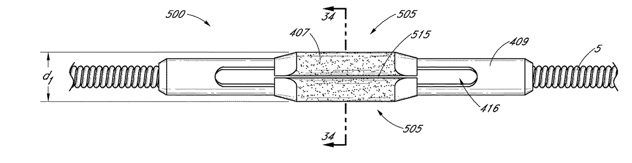
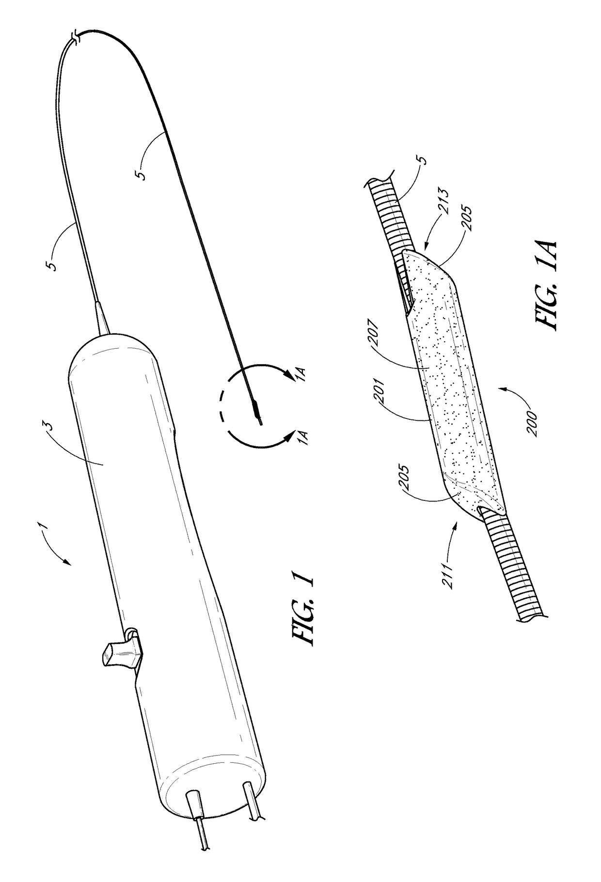
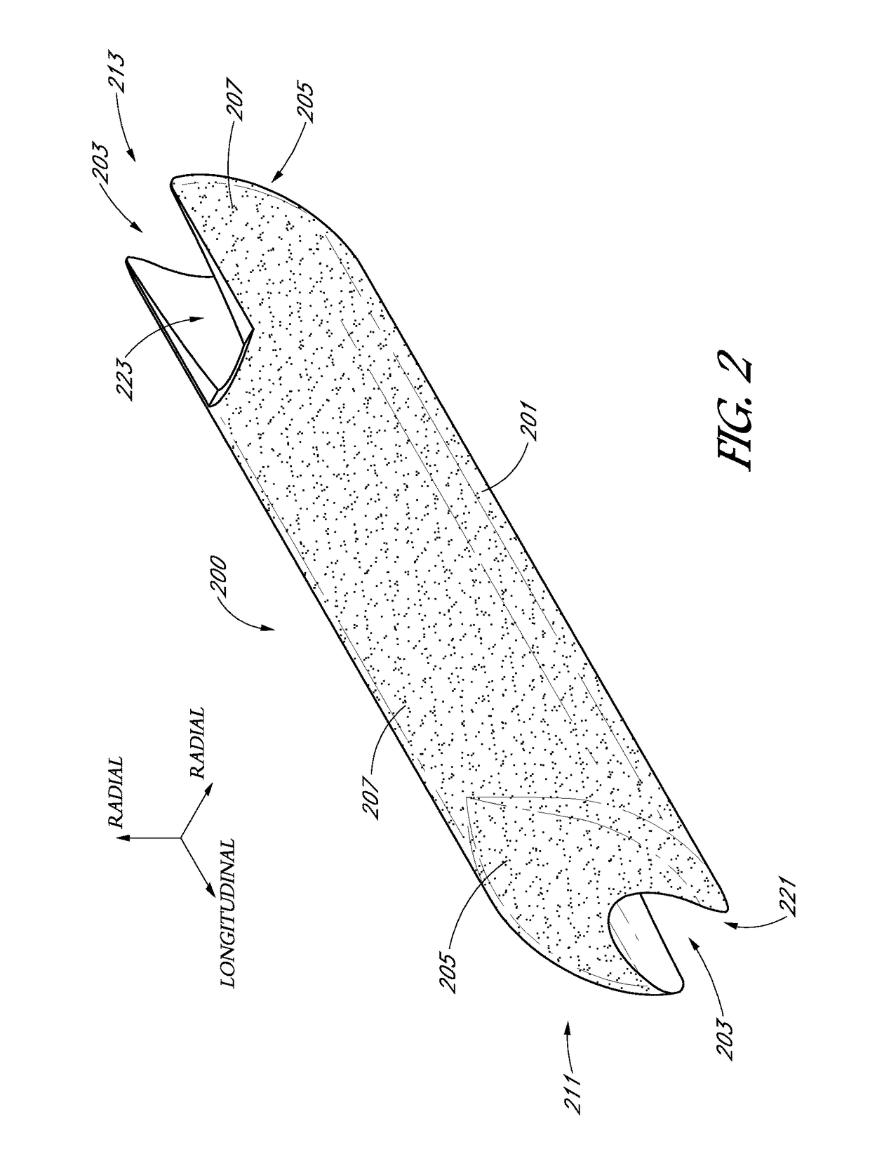
[0006]The present disclosure is directed to novel bead geometries that can provide improved sanding efficiencies in atherectomy procedures. One embodiment is a high-speed rotational atherectomy device for opening a stenosis in an artery having lumen extending therethrough. The device may comprise a flexible, elongated, rotatable driveshaft. The device may also include guidewire having a maximum diameter less than the diameter of the lumen. In such embodiments the driveshaft may be advanceable over the guidewire. An abrasive element may be disposed on the driveshaft. The abrasive element may have a first center of mass offset from a center of mass of the driveshaft in a first radial direction. The abrasive element may have a second center of mass offset from a center of mass of the driveshaft in a second radial direction. The second center of mass may be pos...
PUM
| Property | Measurement | Unit |
|---|---|---|
| length | aaaaa | aaaaa |
| length | aaaaa | aaaaa |
| length | aaaaa | aaaaa |
Abstract
Description
Claims
Application Information