This helps you quickly interpret patents by identifying the three key elements:
Problems solved by technology
Method used
Benefits of technology
[0015]Some of the embodiments described herein may provide one or more of the following advantages. First, some embodiments of the rotational atherectomy devices and systems operate with a stable and predictable rotary motion profile for enhanced atherectomy performance. That is, when the device is being rotated in operation, the eccentric abrasive element follows a predefined, consistent orbital path (offset from an axis of rotation of the device) while the stability elements and other portions of the device remain on or near to t
Problems solved by technology
This limits the flow of oxygen-rich blood to organs and other parts of the body.
Peripheral artery disease (PAD) can be serious because without
Method used
Image
Click on the blue label to locate the original text in one second.
Reading with bidirectional positioning of images and text.
Examples
Embodiment Construction
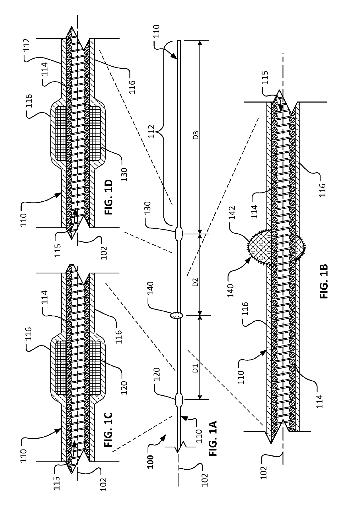
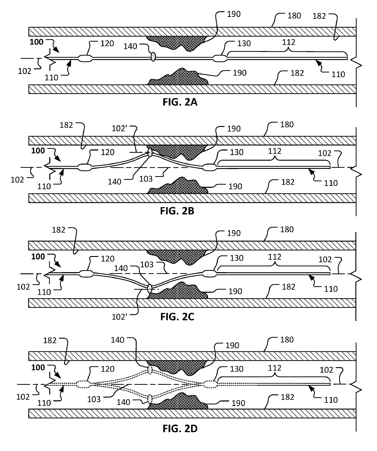
[0036]Referring to FIG. 1A, in some embodiments a rotational atherectomy device 100 can include a drive shaft 110, a proximal stability element 120, a distal stability element 130, and an eccentric abrasive element 140. In this embodiment, the stability elements 120 and 130 have a center of mass that is axially aligned with a central longitudinal axis 102 of the drive shaft 110 while the eccentric abrasive element 140 has a center of mass that is axially offset from central longitudinal axis 102 of the drive shaft 110. As will be described further below, the rotational atherectomy device 100 is configured to remove some or all of a stenotic lesion from within a vessel of a patient. As the rotational atherectomy device 100 is rotated about its longitudinal axis 102, centrifugal force will cause the eccentric abrasive element 140 to follow a transverse circular orbit around the longitudinal axis. The orbiting eccentric abrasive element 140 will contact the stenotic lesion to ablate th...
PUM
Abstract
This document describes rotational atherectomy devices and systems for removing or reducing stenotic lesions in blood vessels by rotating an abrasive element within the vessel to partially or completely remove the stenotic lesion material.
Description
CLAIM OF PRIORITY[0001]This application is a continuation of U.S. patent application Ser. No. 16 / 151,531 filed Oct. 4, 2018, which is a continuation of U.S. patent application Ser. No. 16 / 150,711 filed Oct. 3, 2018, which is a continuation of U.S. patent application Ser. No. 16 / 150,003 filed on Oct. 2, 2018, which is a continuation of U.S. patent application Ser. No. 16 / 148,347 filed on Oct. 1, 2018, which is a continuation of U.S. patent application Ser. No. 16 / 142,583 filed on Sep. 26, 2018, which is a continuation of U.S. patent application Ser. No. 15 / 707,690 filed on Sep. 18, 2017, which is a divisional application and claims priority to U.S. patent application Ser. No. 14 / 155,549, filed on Jan. 15, 2014, the entire contents of which are hereby incorporated by reference.TECHNICAL FIELD[0002]This document relates to rotational atherectomy devices and systems for removing or reducing stenotic lesions in blood vessels, for example, by rotating an abrasive element within the vessel...
Claims
Application Information
Patent Timeline
Application Date:The date an application was filed.
Publication Date:The date a patent or application was officially published.
First Publication Date:The earliest publication date of a patent with the same application number.
Issue Date:Publication date of the patent grant document.
PCT Entry Date:The Entry date of PCT National Phase.
Estimated Expiry Date:The statutory expiry date of a patent right according to the Patent Law, and it is the longest term of protection that the patent right can achieve without the termination of the patent right due to other reasons(Term extension factor has been taken into account ).
Invalid Date:Actual expiry date is based on effective date or publication date of legal transaction data of invalid patent.