Devices, systems, and methods for removing stenotic lesions from vessels
Active Publication Date: 2009-08-13
3DT HLDG
View PDF42 Cites 48 Cited by
Summary
Abstract
Description
Claims
Application Information
AI Technical Summary
This helps you quickly interpret patents by identifying the three key elements:
Problems solved by technology
Method used
Benefits of technology
[0017]In at least one exemplary method for removing a stenotic lesion of a vessel of the present disclosure, the method comprises the steps of measuring a first luminal size parameter at a first location within a vessel lumen, measuring a second luminal size parameter at a second location within the vessel lumen, determining a preferred second luminal size parameter based upon the first luminal size parameter and the second luminal size parameter, and positioning a treatment device at or near the second location. In at least one method, the method further comprises the steps of operating the treatment device to increase the second luminal size parameter and measuring a then-current luminal size parameter at the second location. After the then-current luminal size parameter at the second locat
Problems solved by technology
It is likely to produce angina pectoris, heart attack or both.
Although it appears that progression of AS can be more rapid in patients with degenerative calcific disease than in those with congenital or rheumatic disease, it is not possible to predict the rate of progression in an individual patient.
Problems with Current Aortic Valve Area Measurements
Such patients can be difficult to distinguish from those with low cardiac output and only mild to moderate AS.
Although valve resistance is less sensitive to flow than valve area, resistance calculations have not been proved to be substantially better than valve area calculatio
Method used
Image
Click on the blue label to locate the original text in one second.
Reading with bidirectional positioning of images and text.
Examples
Embodiment Construction
[0038]Reference will now be made to the embodiments illustrated in the drawings and specific language will be used to describe the same. It will nevertheless be understood that no limitation of scope is intended by the description of these embodiments.
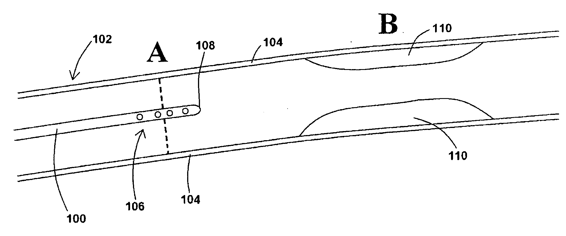
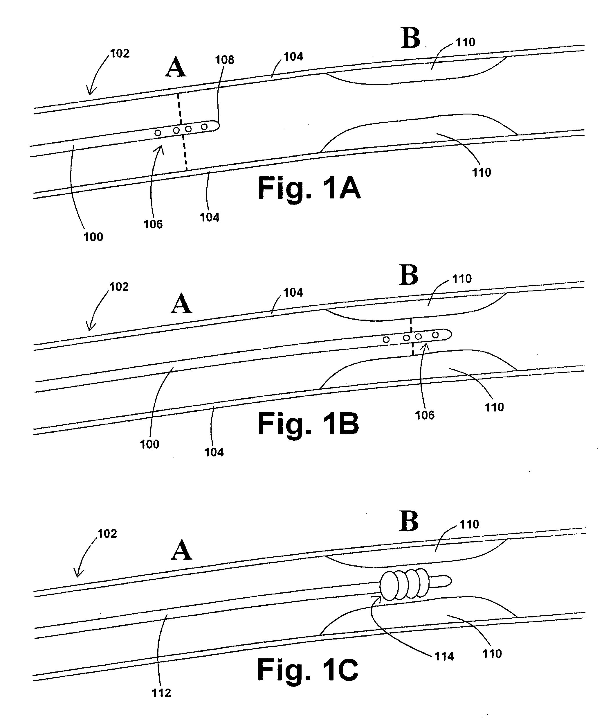
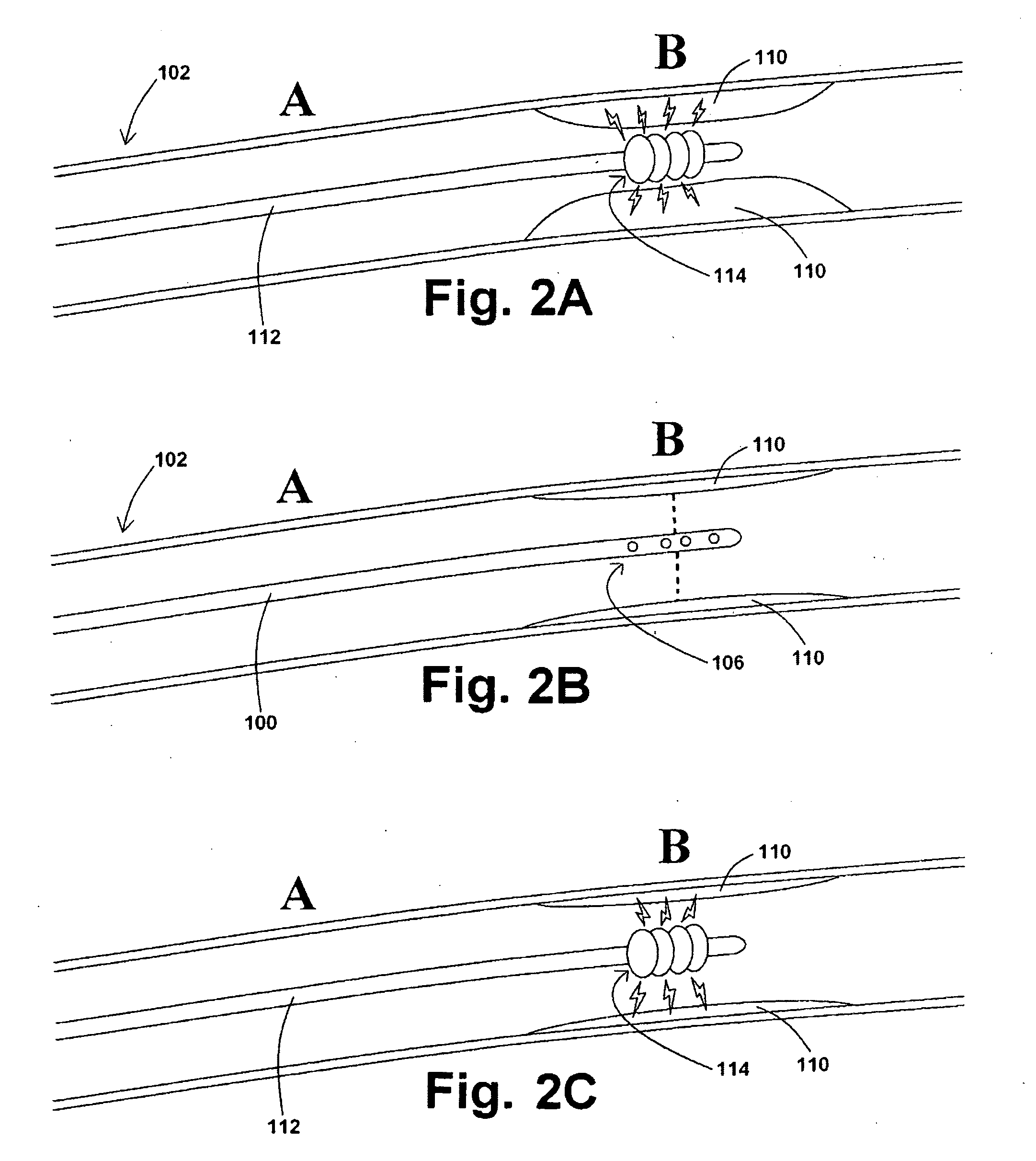
[0039]In at least one embodiment of a method for removing a stenotic lesion of a vessel, the method comprises the steps of measuring at least two luminal parameters, determining a preferred luminal size parameter, and operating a treatment device to increase at least one of the luminal parameters.
[0040]In at least one exemplary method for removing a stenotic lesion of a vessel, the method comprises the steps of measuring a first luminal size parameter at a first location within a vessel lumen, measuring a second luminal size parameter at a second location within the vessel lumen, determining a preferred second luminal size parameter based upon the first luminal size parameter and the second luminal size parameter, and positioning a tre...
PUM
Abstract
The present application provides various devices, systems, and methods for removing stenotic lesions from vessels. In at least one embodiment of an exemplary device, the device comprises at least one sizing portion and at least one treatment portion. Such a device may be useful to, for example, remove a stenotic lesion from a vessel by positioning the device within a vessel lumen, operating the sizing portion to obtain luminal size parameter data, operating the treatment portion at a location within the vessel lumen at or near a stenotic lesion, and ceasing operation of the treatment portion when the luminal size parameter data indicates a preferred luminal size parameter.
Description
PRIORITY[0001]This U.S. Utility patent application is a continuation-in-part application of, and claims priority to, copending U.S. patent application Ser. No. 12 / 098,242, filed Apr. 4, 2008, which is a continuation-in-part application of, and claims priority to, copending U.S. patent application Ser. No. 11 / 891,981, filed Aug. 14, 2007, which is a divisional application of, and claims priority to, U.S. patent application Ser. No. 10 / 782,149, filed Feb. 19, 2004, which issued as U.S. Pat. No. 7,454,244 on Nov. 18, 2008, which claims priority to U.S. Provisional Patent Application Ser. No. 60 / 449,266, filed Feb. 21, 2003, to U.S. Provisional Patent Application Ser. No. 60 / 493,145, filed Aug. 7, 2003, and to U.S. Provisional Patent Application Ser. No. 60 / 502,139, filed Sep. 11, 2003. The contents of each of these applications are hereby incorporated by reference in their entirety into this disclosure.BACKGROUND[0002]The disclosure of the present application relates generally to devic...
Claims
Application Information
Patent Timeline
Application Date:The date an application was filed.
Publication Date:The date a patent or application was officially published.
First Publication Date:The earliest publication date of a patent with the same application number.
Issue Date:Publication date of the patent grant document.
PCT Entry Date:The Entry date of PCT National Phase.
Estimated Expiry Date:The statutory expiry date of a patent right according to the Patent Law, and it is the longest term of protection that the patent right can achieve without the termination of the patent right due to other reasons(Term extension factor has been taken into account ).
Invalid Date:Actual expiry date is based on effective date or publication date of legal transaction data of invalid patent.