
Electronic device with manual operation button

a technology of electronic devices and buttons, applied in the direction of electric switches, basic electric elements, electric apparatus, etc., can solve the problems of high molding accuracy, difficult to increase the size of the manual operation plane b>104, and difficult to expand the operable region, so as to improve the operability of the receiver and improve the exterior design

Inactive Publication Date: 2007-02-06
ORION ELECTRIC CO LTD
View PDF6 Cites 17 Cited by
  • Summary
  • Abstract
  • Description
  • Claims
  • Application Information

AI Technical Summary

Benefits of technology

"The present invention aims to provide an electronic device with a manual operation button that has a wide operable region, is cost-effective, and prevents the button from protruding from the casing. The invention achieves this by integrating a manual operation button with a holder, a switch pressing portion, and a hinge portion, which allows the button to have a mounting hole on the casing and a wide operable region. Additionally, a stopper means can be added to limit the force in which the button presses the switch. The invention also includes a television receiver with a manual operation button that has a large operable region and improved exterior design."

Problems solved by technology

However, since according to patent document 1 and the manual operation button 102 having the prior art structure, the hinge portion 107 is out of range of the outer projection plane of the manual operation plane 104, it is difficult to increase the size of the manual operation plane 104, or in other words, it is difficult to enlarge the operable region.
Furthermore, since the manual operation plane 104 requiring a high molding accuracy to be provided with characters and patterns is integrally molded with other components that do not require such high molding accuracy as the manual operation plane 104, there is a drawback in that the whole manual operation button 102 must be formed with high molding accuracy, by which the molding costs are increased.

Method used


Image

  • Electronic device with manual operation button
  • Electronic device with manual operation button
  • Electronic device with manual operation button

Examples


Embodiment Construction

[0037]Now, the preferred embodiments for carrying out the present invention will be described with reference to the drawings.

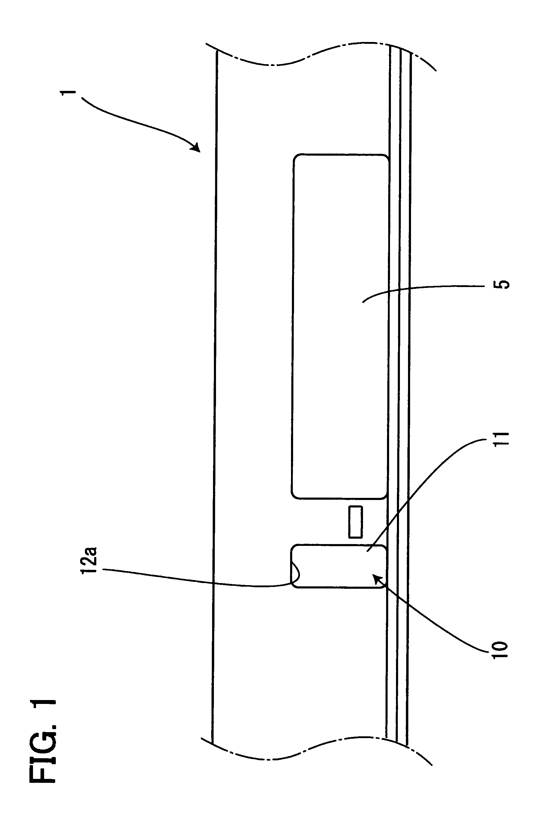
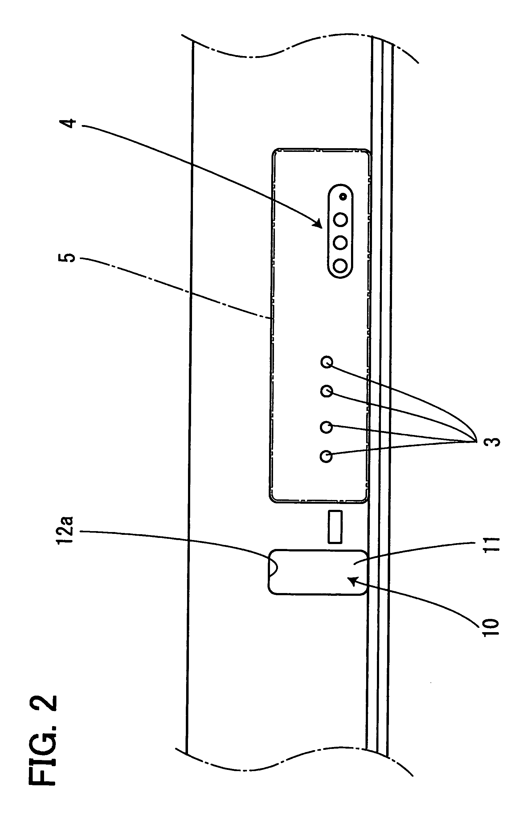
[0038]FIG. 1 is a front view of an electronic device, and according to the present embodiment, the electronic device to which the invention is applied is a television receiver. On the front face of a casing 1 of the television receiver are arranged a plurality of manual operation switches 3 for manually adjusting the volume and switching channels and connecting terminals 4 for connecting cables enabling signals to be input from or output to other electronic devices. These manual operation switches 3 and connecting terminals 4 are covered by a cover 5 capable of being opened and closed via a spindle not shown as supporting point. Adjacent to the cover 5 is arranged a manual operation button 10 for manually operating a switch 6 to turn the main power on and off.

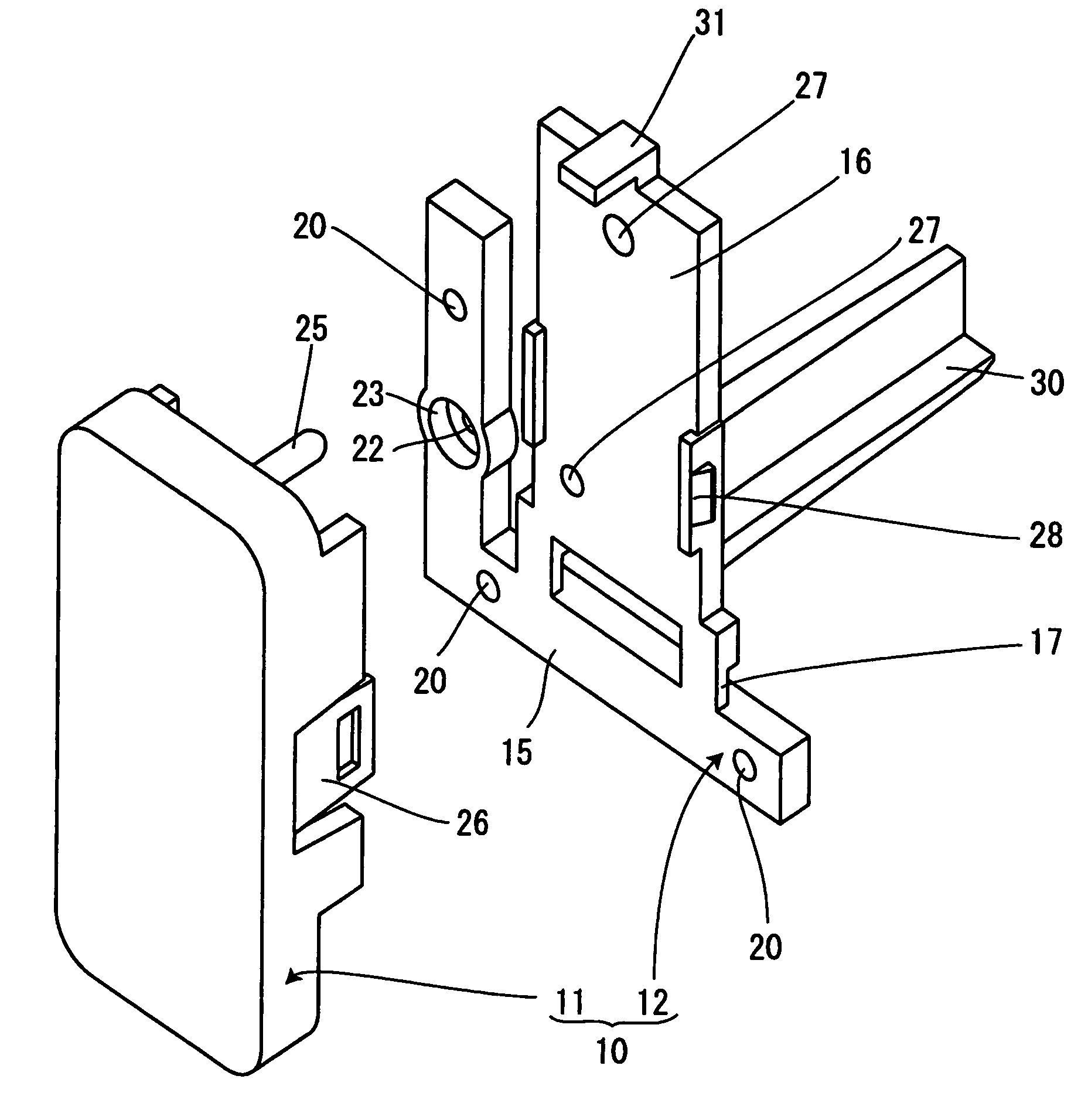
[0039]The manual operation button 10 is composed of a manual operation plane 11, a holder 12 to which ...


PUM


Abstract

The invention provides a manual operation button having a large operable area. A manual operation button is composed of a manual operation plane, a holder for assembling the manual operation plane and a stopper for fixing the holder to a casing. The casing has a mounting hole having substantially the same size and shape as the manual operation plane, so that when the manual operation plane is assembled to the mounting hole, the manual operation plane forms a substantially continuous flat plane with the casing. The holder includes a substantially L-shaped mounting portion for mounting to the casing, a flat plate-like mounting plane for mounting the manual operation plane, and a hinge portion connecting the mounting portion and the mounting plane. The whole width of the hinge portion is disposed within the outer projection plane of the manual operation plane.

Description

[0001]The present application is based on and claims priority of Japanese patent application No. 2005-098752 filed on Mar. 30, 2005, the entire contents of which are hereby incorporated by reference.BACKGROUND OF THE INVENTION[0002]1. Field of the Invention[0003]The present invention relates to a manual operation button of an electronic device, and more specifically, relates to a power button disposed on a front face of a television receiver.[0004]2. Description of the Related Art[0005]Heretofore, an arrangement of the type disclosed in Japanese patent application No. 2005-50750 (patent document 1) utilizing a bendable thin hinge has been adopted in manual operation buttons of electronic devices, since it exerts the required functions via a simple assembly operation and without using metal components such as spindles and springs.[0006]One exemplary structure of such prior art manual operation button adopting the above hinge arrangement and used in electronic devices such as the tele...

Claims


Application Information

Patent Timeline
Patent Type & Authority Patents(United States)
IPC IPC(8): H01H13/70
CPCH01H21/285
Inventor YAMAMOTO, MASATERU
Owner ORION ELECTRIC CO LTD
Learn More