Injection mould for studying tool box stationery series

A technology for injection molds and stationery, which is applied in the field of injection molds for school kits, can solve the problems of resource waste and low efficiency, and achieve the effects of improving production efficiency, improving injection molding quality, and preventing mold collisions

Pending Publication Date: 2019-06-11
福建省靖虹模具科技有限公司
View PDF19 Cites 11 Cited by
  • Summary
  • Abstract
  • Description
  • Claims
  • Application Information

AI Technical Summary

Problems solved by technology

[0004] However, the plastic tray injection molding mold provided in the above technical solution still has many disadvantages in actual use, such as the need for mold matching during injection molding, which has low efficiency, and a set of molds can only produce one product, resulting in waste of resources.

Method used


Image

  • Injection mould for studying tool box stationery series
  • Injection mould for studying tool box stationery series
  • Injection mould for studying tool box stationery series

Examples


Embodiment 1

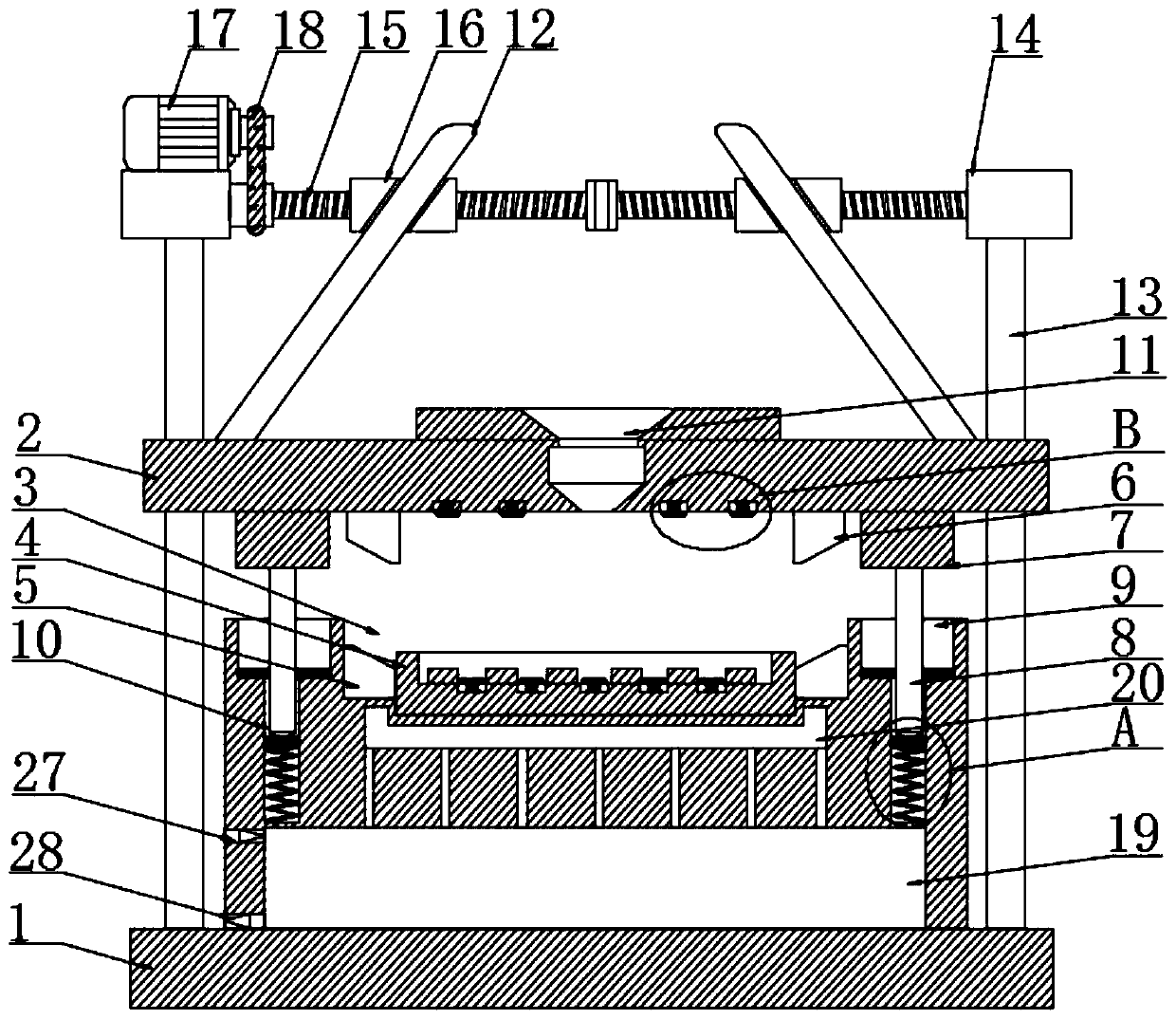
[0025] according to Figure 1-3 The shown injection mold of a series of school kit stationery includes a lower mold base 1, the top of the lower mold base 1 is provided with an upper mold base 2, and the top of the lower mold base 1 is provided with a first groove 3. The middle part of the first groove 3 is provided with a card slot, and an injection molding template 4 is movably connected in the clip groove, and a first clamping block 5 is movably connected between the inner wall of the first groove 3 and the injection molding template 4. The bottom of the mold base 2 is fixedly connected with a second block 6, and the outer side of the second block 6 is fixedly connected with a protrusion 7, and the bottom of the protrusion 7 is fixedly connected with a limit pin 8, and the outer side of the first groove 3 is provided There is a second groove 9, the bottom of the second groove 9 is provided with a limit hole 10, the top of the upper mold base 2 is provided with an injection ...

Embodiment 2

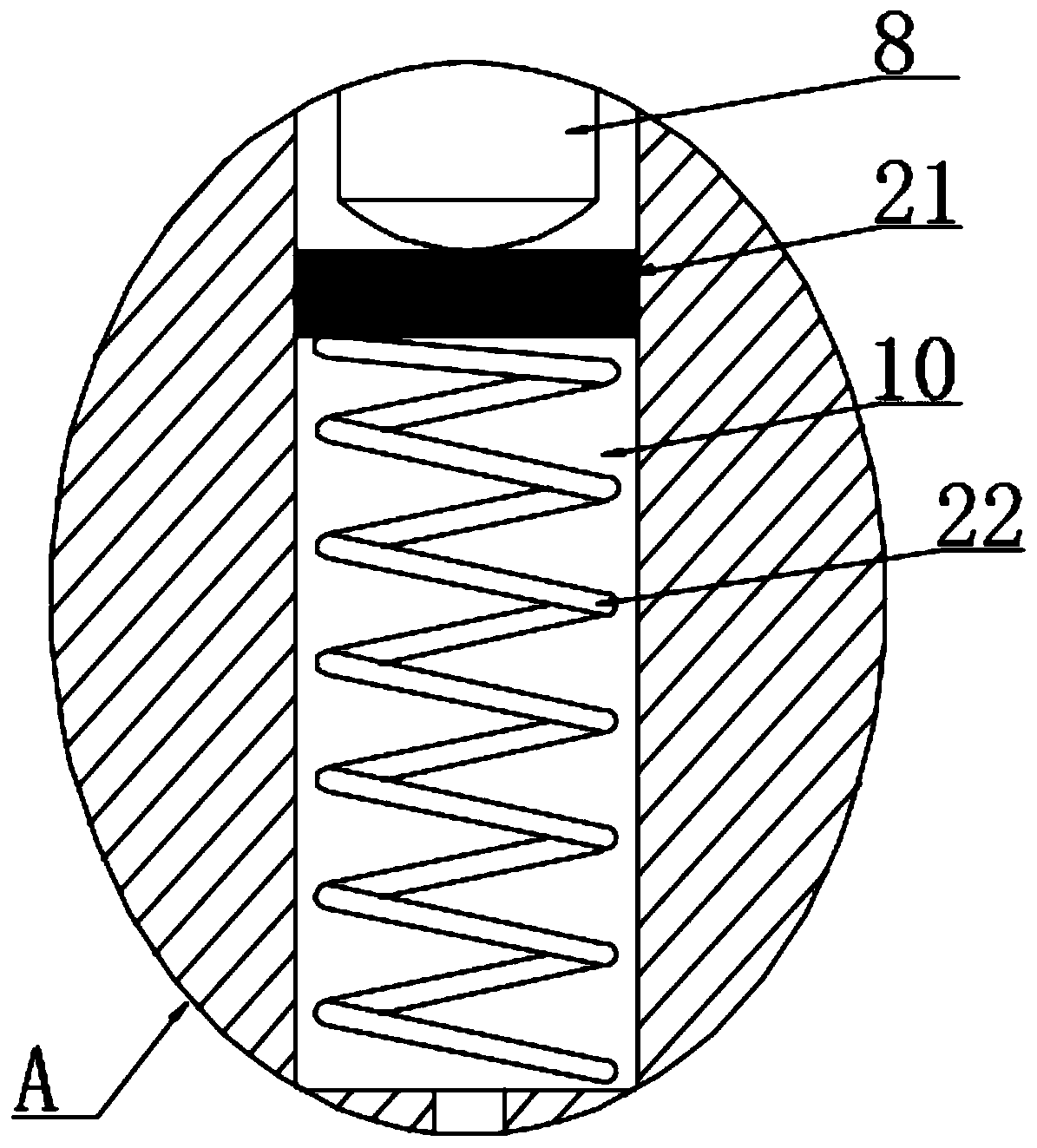
[0028] according to figure 2 As shown in the injection mold of a school kit stationery series, the lower mold base 1 is provided with a cooling liquid tank 19, and the bottom of the slot is provided with a cooling tank 20, and the cooling liquid tank 19 is connected with the cooling tank 20 are connected with a number of evenly distributed first through holes, and a second through hole is provided between the bottom of the limiting hole 10 and the coolant tank 19, and a piston 21 is slidably connected in the limiting hole 10. A first spring 22 is arranged between the piston 21 and the bottom of the limiting hole 10, which communicates with the cooling box 20 through the cooling box 20, so that the temperature of the cooling box 20 can be kept at a low temperature. When injection molding, the limiting pin 8 is inserted into the limiting hole 10. Let the piston 21 slide down to compress the gas so that the coolant enters the cooling box 20 from the first through hole to cool th...


PUM


Abstract

The invention discloses an injection mould for studying tool box stationery series, and particularly relates to the technical field of moulds. The injection mould for the studying tool box stationeryseries comprises a lower mould seat. An upper mould seat is arranged at the top of the lower mould seat, a first groove is formed in the top end of the lower mould seat, a clamping groove is formed inthe middle of the first groove, an injection mould plate is movably connected into the clamping groove, and a first clamping block is movably connected between the inner wall of the first groove andthe injection mould plate. According to the injection mould for the studying tool box stationery series, the clamping groove is connected with the injection mould plate in a clamped mode, the injection mould plate is fixed through the first clamping block, the mould plate is conveniently replaced, the mould manufacturing cost is lowered, the motor rotates and is connected with a connecting threaded rod in a transmission mode through a conveyor belt, thus two moving sleeves move oppositely, a pulling rod slides in a sliding sleeve, the upper mould seat is pulled to slide on the outer side of the sliding rod, the lower mould seat and the upper mould seat conveniently work in a corresponding mode, the production efficiency is improved, a raised block is matched with a second groove, a limiting pin and a limiting hole are matched, the raised block, the second groove, the limiting pin and the limiting hole are matched with a buffering cushion to reduce vibration, the upper mould seat is stabilized advantageously, mould crushing is avoided, and the injection quality is improved.

Description

technical field [0001] The invention relates to the technical field of molds, and more specifically, the invention relates to an injection mold for a school kit box. Background technique [0002] The school kit box is a special storage box for primary schools. The school kit box stores some small sticks and balls for counting, or triangular boards. With the improvement of education level, the school kit box has become an indispensable part of education. The box is usually made of plastic material. [0003] The Chinese patent of patent application publication number CN 108790046 A discloses a plastic tray injection molding mold, including a push plate, the center of the push plate is provided with a through hole, the upper mold is arranged on the top of the push plate, and the lower part of the upper mold is provided with a concave hole. Groove, the upper part of the core passes through the through hole of the push plate, and its upper part is inserted into the groove of the...

Claims


Application Information

Patent Timeline
Patent Type & Authority Applications(China)
IPC IPC(8): B29C45/26B29C45/40B29C45/66B29C45/73B29C45/17
Inventor 钱建根王炜杰
Owner 福建省靖虹模具科技有限公司
Why Eureka
Try Eureka