
Method and apparatus for downhole quantification of methane using near infrared spectroscopy

a methane and near infrared spectroscopy technology, applied in the direction of optical radiation measurement, survey, borehole/well accessories, etc., can solve the problems of wasting rig time, contamination of drilling mud filtrate, and little reason to collect formation fluid samples in the sample tank

Inactive Publication Date: 2007-02-06
BAKER HUGHES INC
View PDF17 Cites 52 Cited by
  • Summary
  • Abstract
  • Description
  • Claims
  • Application Information

AI Technical Summary

Benefits of technology

[0009]Unlike Mullins U.S. Pat. No. 6,476,384 (Mullins '384), which describes a method for determining GOR based on two wavelengths, the first located near a methane-gas spectral peak and the second located near a liquid-hydrocarbon spectral peak (representing oil), the present invention uses two wavelengths that are both near a single spectral peak for methane (i.e., two regions of the same methane peak). Also, unlike Mullins '384, which based its spectral GOR determination equations on a training set of binary mixtures of n-heptane (representing oil) and methane, the present invention bases its spectral GOR equations on synthetic mixtures of methane and dead crude oils. A dead crude oil is one for which little or no gas remains in the crude oil because it was not stored under pressure and therefore the gas in

Problems solved by technology

Thus, samples taken from the formation contain drilling mud filtrate contamination.
If it is known that there is too much filtrate contamination in the sample (e.g., more than about 10% filtrate), then there is little reason to collect a formation fluid sample in a sample tank.
On the other hand, if by pumping for a relatively long time, it is possible to achieve an only slightly better filtrate contamination level, an operator may end up wasting very expensive rig time and also risks the very costly possibility of allowing a tool to become stuck in the wellbore.

Method used


Image

  • Method and apparatus for downhole quantification of methane using near infrared spectroscopy
  • Method and apparatus for downhole quantification of methane using near infrared spectroscopy
  • Method and apparatus for downhole quantification of methane using near infrared spectroscopy

Examples


Embodiment Construction

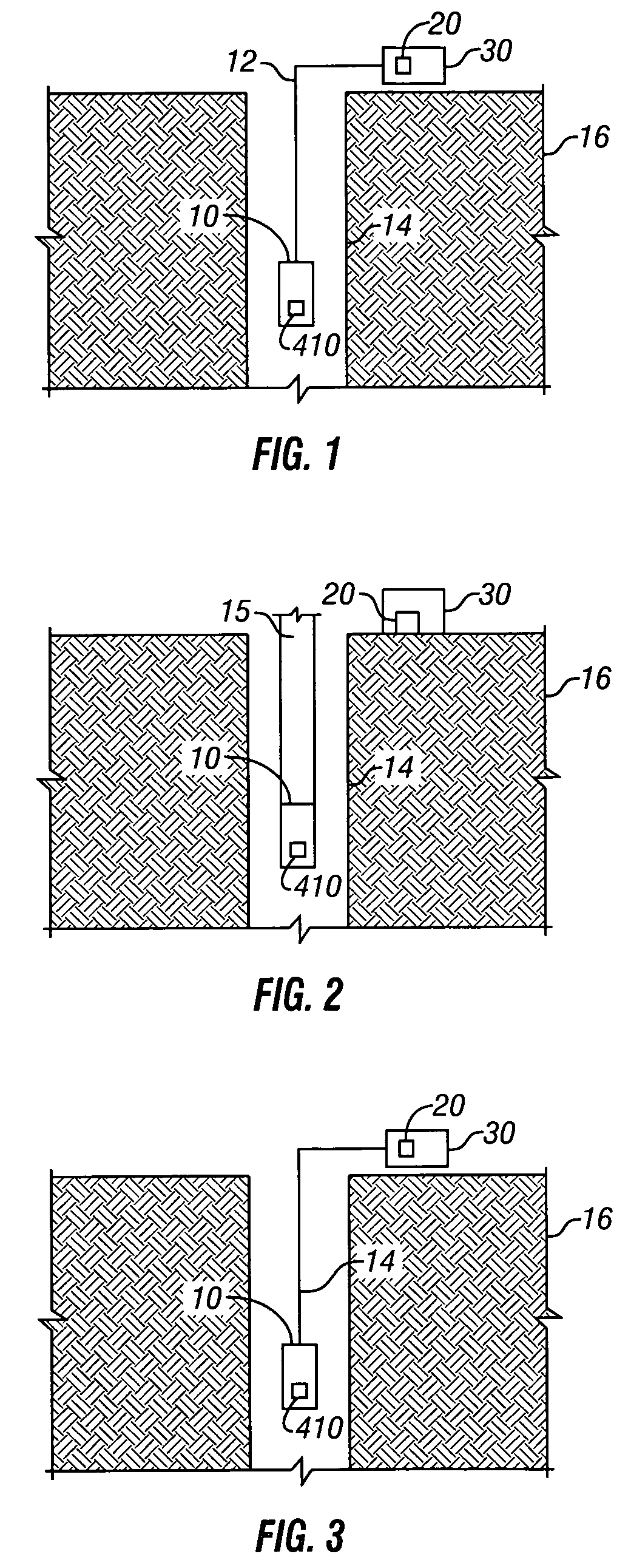
[0019]FIG. 1 is a schematic diagram of an exemplary embodiment of the present invention deployed on a wireline in a downhole environment. As shown in FIG. 1, a downhole tool 10 containing a optical analyzer 410 of the present invention is deployed in a borehole 14. The borehole is formed in formation 16. Tool 10 is deployed via a wireline 12. Data from the tool 10 is communicated to the surface to a computer processor 20 with memory inside of an intelligent completion system 30. FIG. 2 is a schematic diagram of a exemplary embodiment of the present invention deployed on a drill string 15 in a monitoring while drilling environment. FIG. 3 is a schematic diagram of an exemplary embodiment of the present invention deployed on a flexible tubing 13 in a downhole environment.

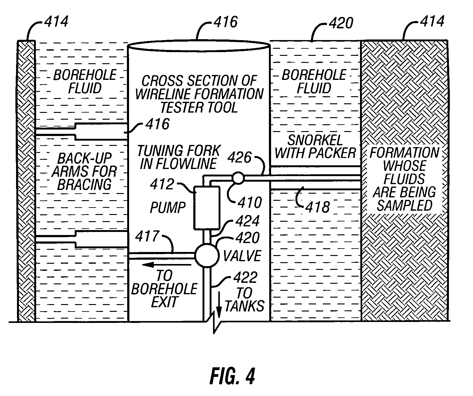
[0020]FIG. 4 is a schematic diagram of an exemplary embodiment of the present invention as deployed from a wireline downhole environment showing a cross section of a wireline formation tester tool. As shown in FIG. 4,...


PUM


Abstract

The present invention describes a unique method and apparatus for applying near-infrared spectroscopy to estimate weight percent of methane in crude oil from which one can then infer gas-oil ratio (GOR) of crude oils downhole in real time while collecting a fluid sample. The correlation equations provided by this invention use two wavelengths, one centered at 1670 and the other centered at 1682 nm. Both wavelengths are primarily sensitive to the methane peak absorption. To significantly improve the fit, non-spectroscopic parameters, such as temperature or pressure, can be included in the correlation equation. Also, this invention can be used to monitor sample cleanup by monitoring the increase in GOR associated with cleanup as a fluid being pumped from the formation transitions from mostly gas-free filtrate to mostly gas-containing crude oil.

Description

CROSS REFERENCE TO RELATED APPLICATIONS[0001]This patent application claims priority from U.S. provisional patent application No. 60 / 454,987 filed on Mar. 14, 2003 entitled “A Method and Apparatus for Downhole Quantification of Methane Using Near Infrared Spectroscopy” by Rocco DiFoggio.FIELD OF THE INVENTION[0002]The invention relates generally to a method and apparatus for quantifying the weight percentage of methane or the gas oil ratio for a crude oil sample downhole by using the sample's absorbance at two specially selected optical channels. The center wavelengths and bandwidths of these channels were selected by a complex simulation.BACKGROUND OF THE INVENTION[0003]In wellbore exploration, typically drilling mud such as oil-based mud and synthetic-based mud are used. Filtrates from these muds generally invade the hydrocarbon bearing formation through the borehole wall. Thus, samples taken from the formation contain drilling mud filtrate contamination. Thus, a sufficient volume...

Claims


Application Information

Patent Timeline
IPC IPC(8): G01V5/08E21B47/10G01N21/35
CPCE21B47/102G01N21/3577G01N21/3504G01N21/359E21B47/113E21B49/088
Inventor DIFOGGIO, ROCCO
Owner BAKER HUGHES INC
Learn More