Method for calibrating the geometry of a multi-axis metrology system

a multi-axis metrology and geometry technology, applied in angle measurement, manufacturing tools, instruments, etc., can solve the problems of comparatively crude wavefront measurement gauge part positioning and stage alignment requirements, method costs are quite high, and the design and cost of metrology equipment are quite high

a multi-axis metrology and geometry technology, applied in angle measurement, manufacturing tools, instruments, etc., can solve the problems of comparatively crude wavefront measurement gauge part positioning and stage alignment requirements, method costs are quite high, and the design and cost of metrology equipment are quite high

US7173691B2Active Publication Date: 2007-02-06QED TECH INT

Image

  • Method for calibrating the geometry of a multi-axis metrology system
  • Method for calibrating the geometry of a multi-axis metrology system
  • Method for calibrating the geometry of a multi-axis metrology system

Examples


Embodiment Construction

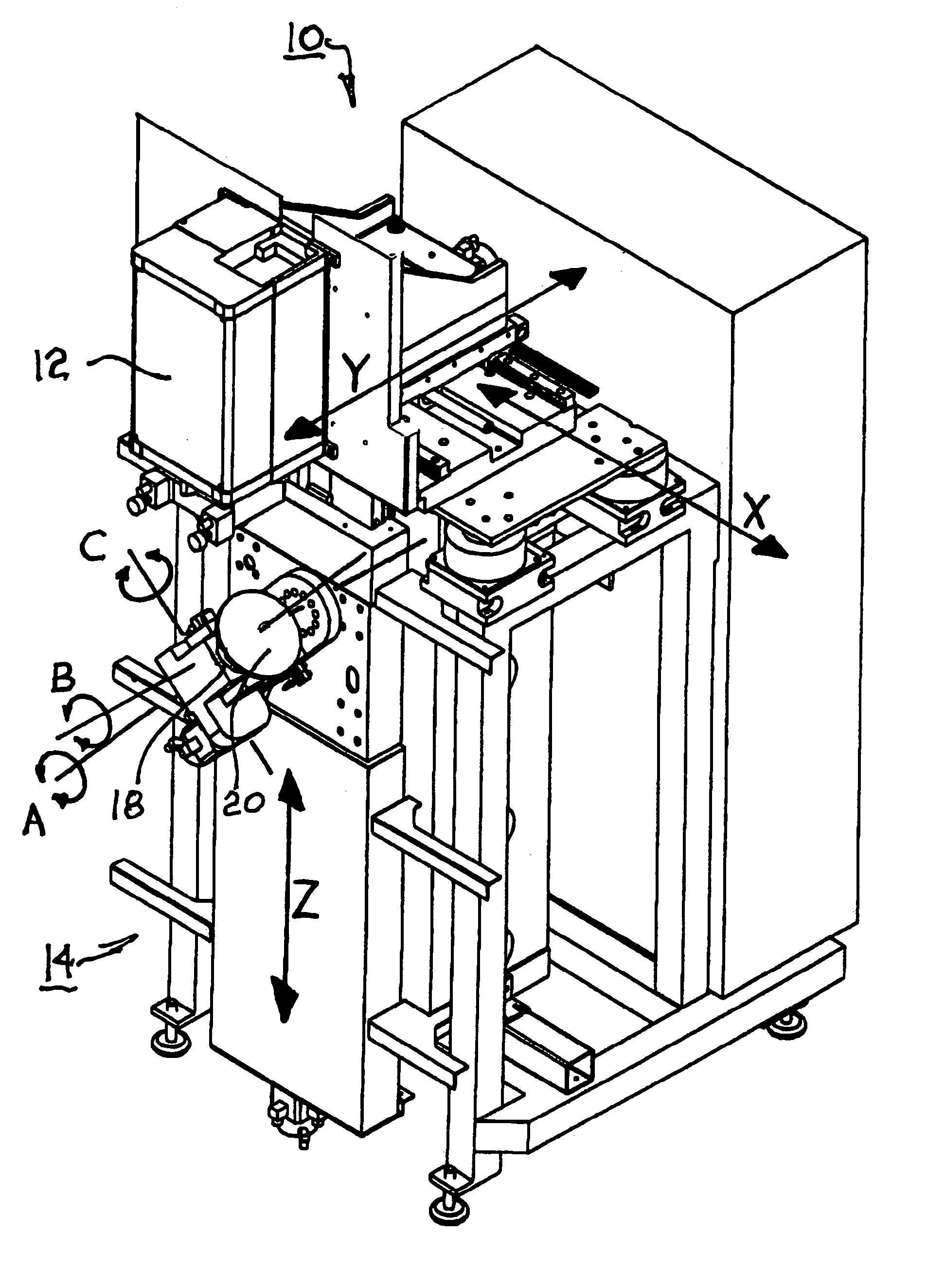
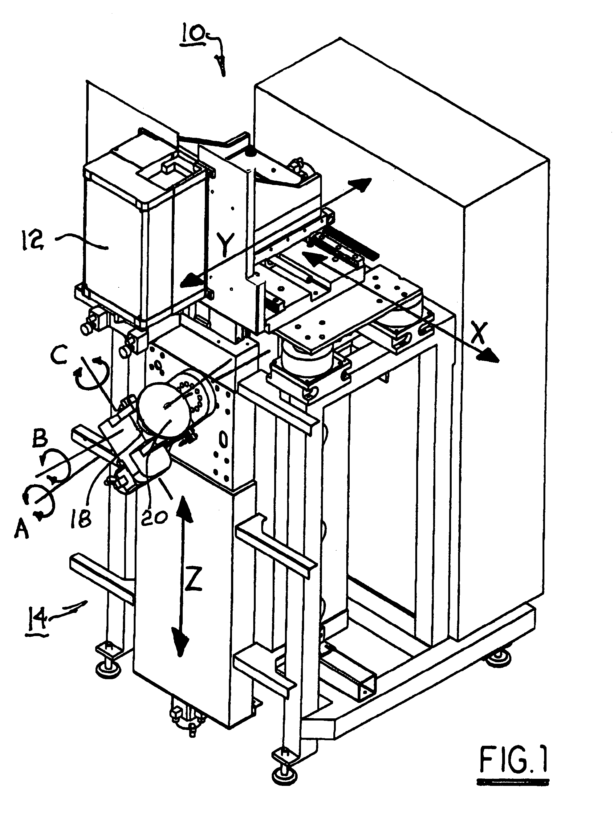
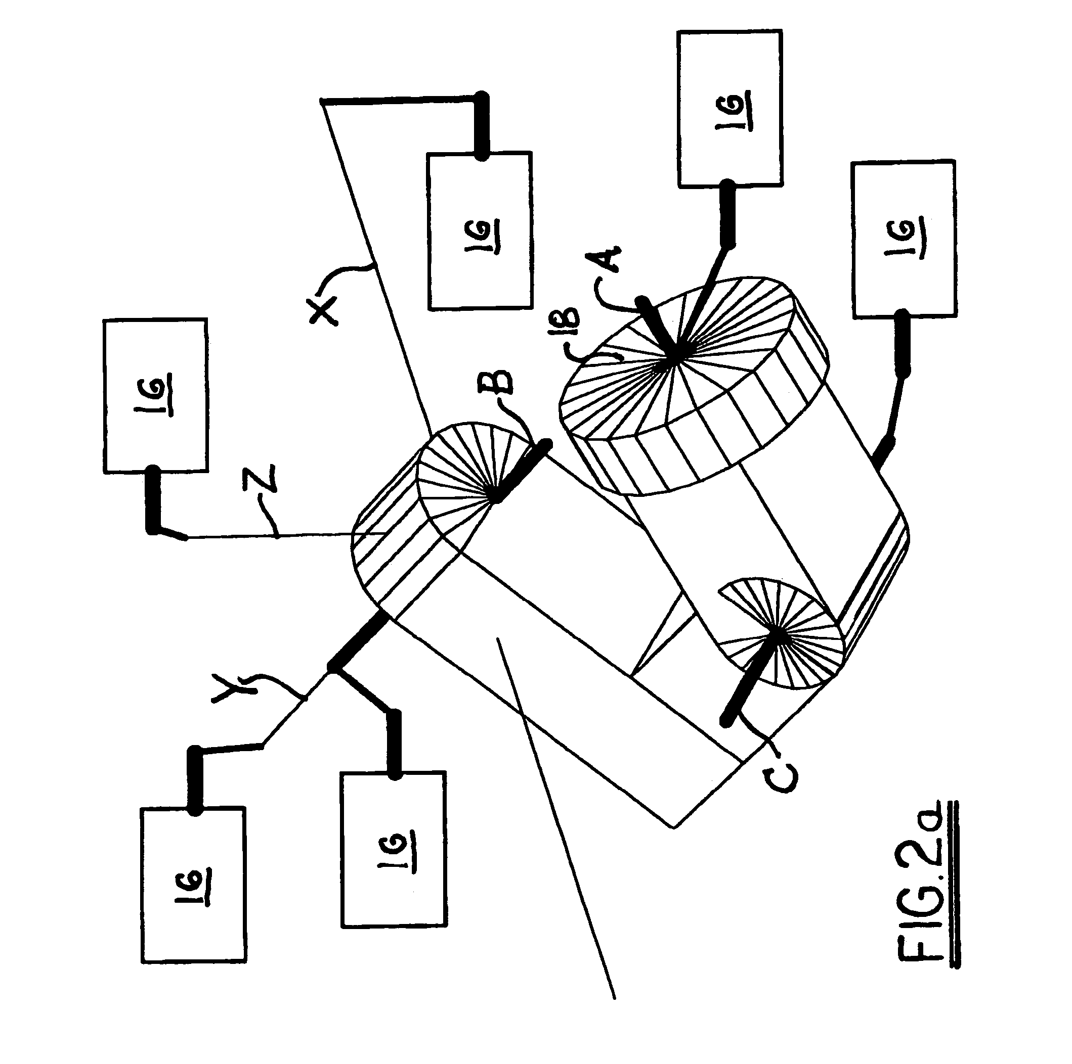
[0040]Referring to FIGS. 1 and 2, a metrology system 10 in accordance with the invention includes a wavefront gauge 12, for example, an interferometer, mounted to (“embedded” in) a multi-axis machine 14 defining a workstation having a stage 18 for receiving and moving a test part 20 during measurement thereof. A configuration of machine motions is shown (FIG. 2a) wherein there are six mechanical axes; three for translation (X, Y, Z) and three for rotation (A, B, C). It should be understood that other configurations of axes (including a different number and / or ordering of the axes) are possible within the scope of this invention. Motion in each of these six axes is independently controllable by, for example, an actuator 16 such as a stepper motor assembly having conventional mounting and gearing. All of the mechanical axes may be under either automatic or manual control. The type of control is not an essential part of the process. The machine axes must position a test part such that ...


PUM


Abstract

A method for calibrating and aligning a metrology system comprising a machine including multi-axis part-positioning means and a wavefront-measuring gauge embedded in the machine. The gauge is used in determining spatial relationships among the translational and rotational axes, between part surface coordinates and machine coordinates, and between machine coordinates embedded gauge coordinates; in calibrating various components of the machine and the embedded gauge; and in aligning itself to the machine. A complete method comprises the steps of coarsely aligning the machine rotary axes with their respective translational axes and setting nominal zero points for the rotary axes; aligning the embedded gauge mainframe to the machine axes; aligning the embedded gauge focal point onto a spindle axis; determining the spatial offsets between the rotary axes when so aligned; precisely aligning the machine rotary axes with their respective translational axes; and setting precise zero points for the rotary axes.

Description

BACKGROUND OF THE INVENTION[0001]1. Field of the Invention[0002]The present invention relates to methods and apparatus for surface and wavefront metrology; more particularly to methods for measurement of surface locations with respect to machine motion axes and the measuring device; and most particularly, to a method for calibration of the geometry of an integrated metrology system comprising a multi-axis CNC mechanical positioning apparatus and an embedded wavefront-measuring gauge.[0003]2. Discussion of the Related Art[0004]In applications of single-point scanning measurement systems and machining, it is extremely important to achieve accurate positioning. Positioning errors in a sensitive direction translate into one-to-one cutting / measuring errors. As a result, considerable effort has been devoted to the manufacture of accurate positioning systems, methods for measuring such accuracies, as well as means for compensation of motion biases such as axis non-orthogonality. Such metho...

Claims


Application Information

Patent Timeline
06 Feb 2007
Publication
US7173691B2
IPC
G01B11/26; G01B11/27; G01C9/00
CPC
B23Q17/22; B23Q17/2495; G01B11/272; G01C9/00
Inventors
MURPHY; FLEIG, JON