Zoom lens, image magnification projection system and video projector using the zoom lens and rear projector and multi-vision system using the video projector

a projection system and zoom lens technology, applied in the field of zoom lens, image magnification projection system and video projector using the zoom lens and the rear projector and multi-vision system using the video projector, to achieve the effect of favorably correcting distortion

Active Publication Date: 2007-02-06
PANASONIC CORP
View PDF17 Cites 23 Cited by
  • Summary
  • Abstract
  • Description
  • Claims
  • Application Information

AI Technical Summary

Benefits of technology

[0011]The present invention was arrived at in order to solve the foregoing problems of the prior art, and it is an object thereof to provide a zoom lens suitable for a projection lens that can have a long back focus, suppress distortion, longitudinal chromatic aberration, and lateral chromatic aberration, and reduce unnecessary light and any change in performance even by changing the projection distance in order to realize a projector that includes a reflection-type spatial optical modulating element and can change the position of a projected image relative to the optical axis of a projection lens, and a projector using the zoom lens.

Problems solved by technology

Moreover, the unnecessary light reflected from the spatial optical modulating element travels toward the zoom lens as projection lens at a large angle with respect to the optical axis.

Method used


Image

  • Zoom lens, image magnification projection system and video projector using the zoom lens and rear projector and multi-vision system using the video projector
  • Zoom lens, image magnification projection system and video projector using the zoom lens and rear projector and multi-vision system using the video projector
  • Zoom lens, image magnification projection system and video projector using the zoom lens and rear projector and multi-vision system using the video projector

Examples


first embodiment

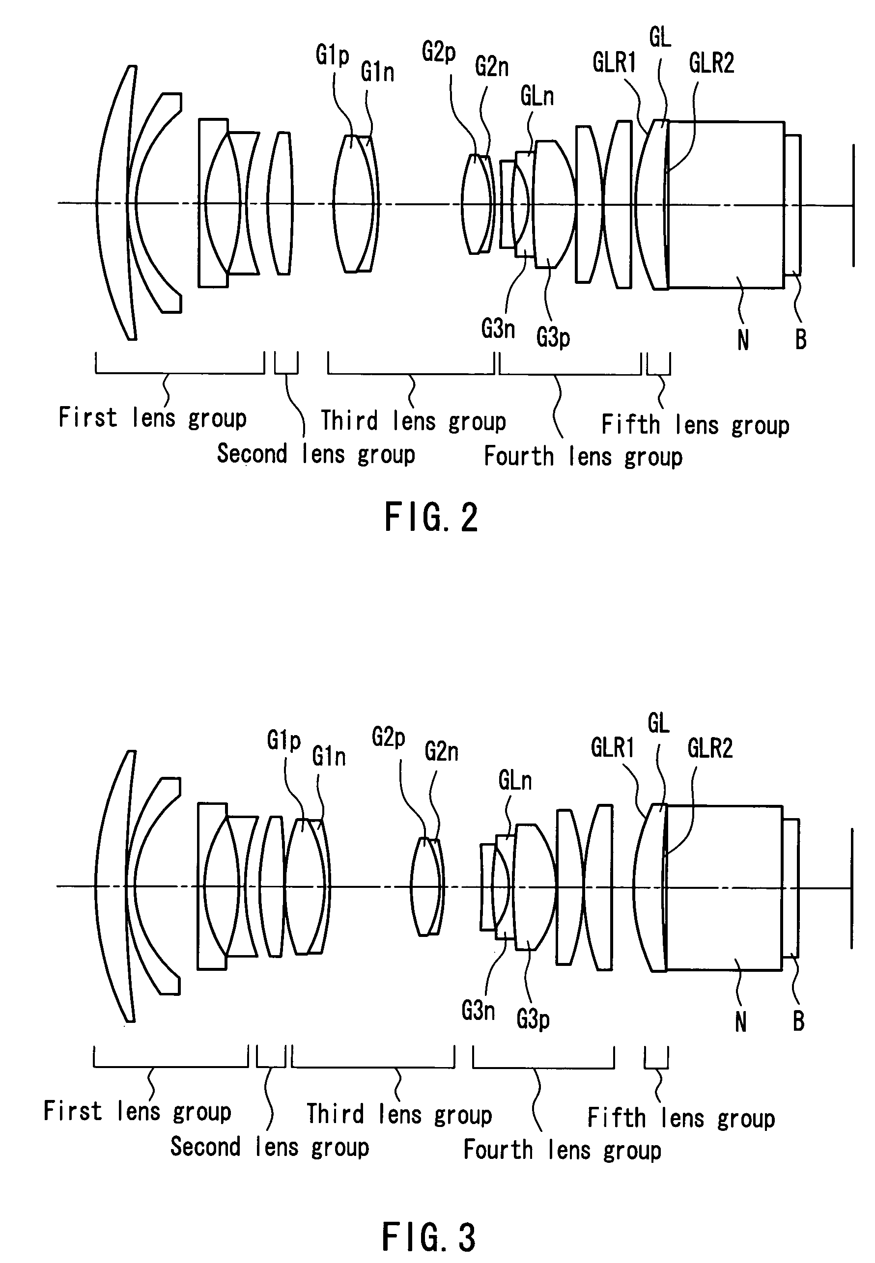
[0151]A zoom lens according to a first embodiment of the present invention will be described with reference to the drawings. FIG. 2 shows the configuration of a zoom lens at the wide-angle end according to the first embodiment of the present invention. FIG. 3 shows the configuration of the zoom lens at the telephoto end according to the first embodiment of the present invention (FIGS. 2 and 3 also show a zoom lens in Example 1, which will be described later).

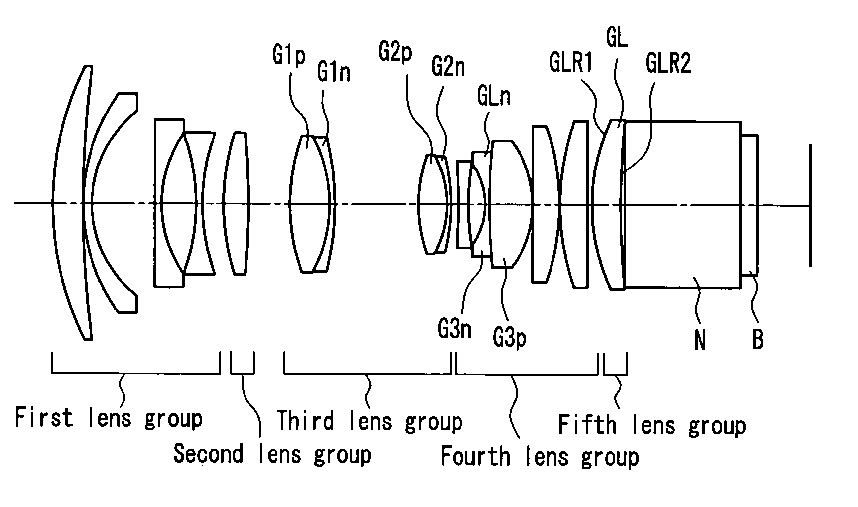
[0152]As shown in FIG. 2, the zoom lens of this embodiment includes a first lens group having a negative refractive power, a second lens group having a positive refractive power, a third lens group having a positive refractive power, a fourth lens group having a negative refractive power, and a fifth lens group having a positive refractive power (five group configuration), arranged in the indicated order from the screen side (on the left side in FIG. 2). In FIG. 2, N denotes a glass block such as a prism, and B denotes a reflect...

example 1

[0161]FIG. 2 shows the configuration of a zoom lens at the wide-angle end in Example 1 according to the first embodiment of the present invention. FIG. 3 shows the configuration of the zoom lens at the telephoto end in Example 1 according to the first embodiment of the present invention.

[0162]In this example, a zoom lens having an F number FNO of 1.7, a focal length f of 23.95 mm, and a half angle of view W of 27.75° at the wide-angle end was designed based on the configuration of the present invention so as not to cause ghosts or reduce the contrast.

[0163]Table 2 shows a specific numerical example. In Table 2, ri denotes the radius of curvature of the lens surfaces, di denotes the lens thickness or the distance between the lens surfaces, ni denotes the refractive index at the d line of the lenses, and νi denotes the Abbe number at the d line of the lenses (theses are also applicable to the another examples described later).

[0164]

TABLE 2Conditional expression (1)(GLR1 / GLnd − Bfw) / fw...

example 2

[0166]FIG. 6 shows the configuration of a zoom lens at the wide-angle end in Example 2 according to the first embodiment of the present invention. FIG. 7 shows the configuration of the zoom lens at the telephoto end in Example 2 according to the first embodiment of the present invention.

[0167]In this example, a zoom lens having an F number FNO of 1.7, a focal length f of 23.90 mm, and a half angle of view W of 27.81° at the wide-angle end was designed based on the configuration of the present invention so as not to cause ghosts or reduce the contrast.

[0168]Table 3 shows a specific numerical example.

[0169]

TABLE 3Conditional expression (1)(GLR1 / GLnd − Bfw) / fw = −0.2678Conditional expression (2)(GLR2 − Bfw) / fw = 10.077Conditional expression (3)fGL / fw = 2.824Conditional expression (4)PgFGL − 0.6457 + 0.0017 ×νdGL = 0.0137Conditional expression (5)PgFGLn = 0.609Conditional expression (6)(PgFGLn − PgFGL) / (νdGLn −νdGL) =−0.0037Conditional expression (7)νdGp1 −νdGn1 = 8.3Conditional express...


PUM


Abstract

The present invention provides a zoom lens that suppresses the generation of unnecessary light and is suitable for a projection lens. The zoom lens is used as a projection lens of a projector in which a prism is located between the projection lens and a spatial optical modulating element B. A lens closest to the spatial optical modulating element B is a meniscus positive lens whose convex surface faces a screen. A refractive index of the meniscus positive lens is 1.75 or more.

Description

TECHNICAL FIELD[0001]The present invention relates to a zoom lens and a projector that magnifies and projects an image of a spatial optical modulating element onto a screen. In particular, the present invention relates to a zoom lens suitable for a projection lens of a projector using a reflection-type spatial optical modulating element, and a projector using the zoom lens.BACKGROUND ART[0002]This type of zoom lens is disclosed, e.g., in JP 2001-311872 A, JP 2000-98222 A, JP 2001-51195 A, and JP 2002-148515 A.[0003]In a projector that uses a transmission-type spatial optical modulating element for three primary colors of red, green and blue, a prism (color composition prism) for composing the three colors is located between a projection lens and a spatial optical modulating element. Because of this, the projection lens requires a long back focus. Since spectral characteristics of the color composition prism are dependent on the incident angle, the projector requires an optical syste...

Claims


Application Information

Patent Timeline
Patent Type & Authority Patents(United States)
IPC IPC(8): G02B9/00G02B15/14G02B15/20G02B15/167G03B21/00
CPCG02B15/177G02B13/22G02B27/0018G02B15/145523G02B15/144511
Inventor KIMURA, SYUNSUKETAKAHASHI, MASAYUKI
Owner PANASONIC CORP
Why Eureka
Try Eureka