Hot to cold steam transformer for turbine systems

a technology of transformers and turbine systems, applied in the direction of machines/engines, mechanical equipment, lighting and heating apparatus, etc., can solve the problems of increasing repairs and downtime, increasing power requirements that are diurnally cyclical, and shortening the life of the turbin

Active Publication Date: 2007-02-13
SIEMENS ENERGY INC
View PDF32 Cites 48 Cited by
  • Summary
  • Abstract
  • Description
  • Claims
  • Application Information

AI Technical Summary

Problems solved by technology

This is because power requirements there are diurnally cyclical and some turbine units are routinely shut down during low power requirement periods, and are restarted when demand increases.
Because thermal stresses upon the metal components of steam turbines are known to adversely affect these components, leading to increased repairs and down time, and to shortened turbine life, various approaches are employed to assure a sufficiently gradual increase in steam temperature during turbine cold starts.
However, it is known that there are limits to the amount of water that may be added through an in-line attemperator.
This may result in less flexibility during startups.
This lack of vaporization results in moisture carryover, where water droplets may travel into the turbine damaging the turbine blades.

Method used


Image

  • Hot to cold steam transformer for turbine systems
  • Hot to cold steam transformer for turbine systems
  • Hot to cold steam transformer for turbine systems

Examples


Embodiment Construction

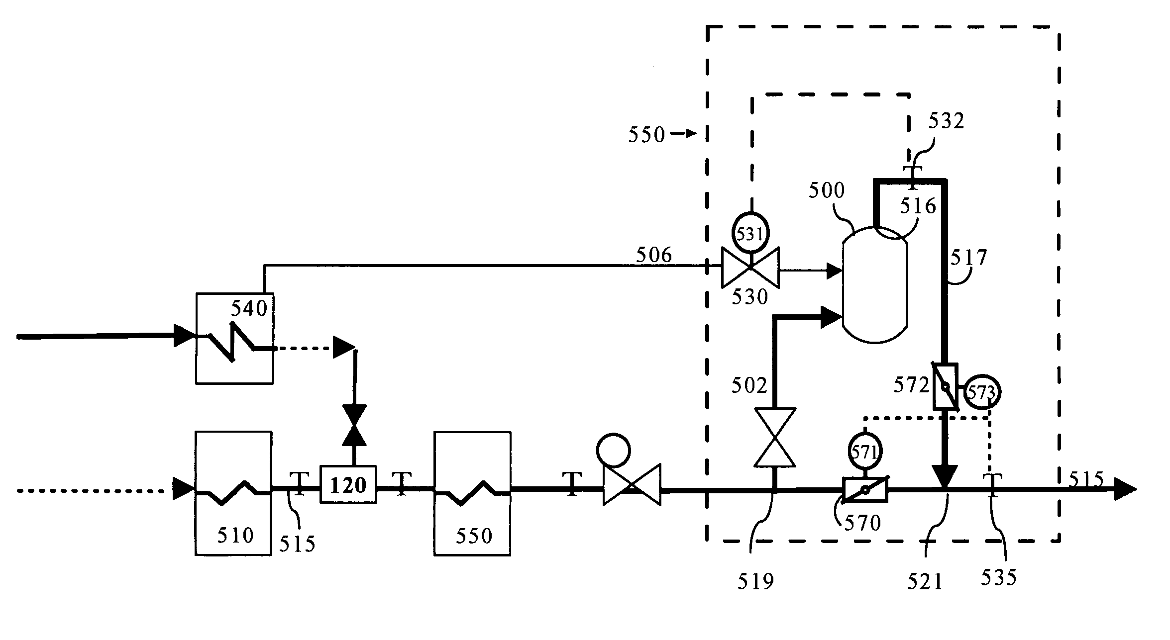
[0019]The present invention is directed to steam turbine facilities and combined cycle turbine facilities in which a flow of steam is cooled by exposure to water in a steam transformer. Thus, the present invention is directed to the entire respective turbine facilities, as well as to the subcomponent systems and apparatuses that are comprised of a steam transformer as defined and claimed herein.

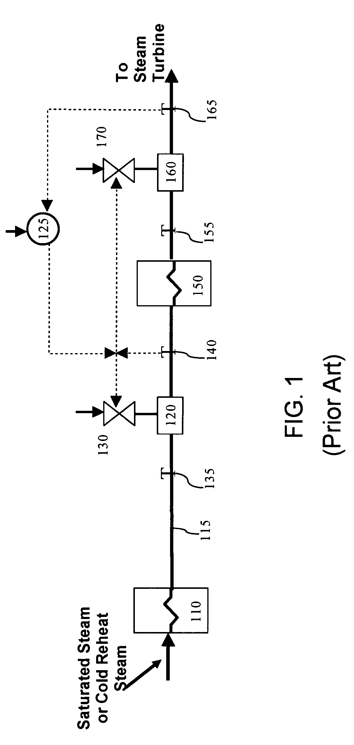
[0020]As used herein, the term “steam-cycle power plant(s)” refers collectively both to steam (i.e., boiler) facilities, and combined cycle turbine facilities (also known as gas and steam-turbine plants). Within such steam-cycle power plants are present a number of distinct steam circuits that direct steam from one component (i.e., superheater, reheater) to another component (i.e., turbines) through conduits.

[0021]As used herein, the term “heater” refers to any heat-generating or heat-transfer component of a steam-cycle power plant, examples of which include a superheater, and a reheater, tha...


PUM


Abstract

A steam transformer (200) receives steam through a steam inlet (203), and the steam is mixed in a mixing zone (231) with water entering through a water inlet (205). Steam cooled by contact with the water exits the steam transformer through a cold steam outlet (216). Between the mixing zone (231) and the cold steam outlet (216) is positioned a demister (214) that restricts the passage of water droplets.The steam transformer (200) is used to condition the steam temperature in steam turbine and combined cycle turbine facilities when adjustment of steam temperature is required, such as for cold starts of turbines. The steam transformer (200) may be installed into a bypass circuit or directly inline. A number of differing configurations and designs are disclosed.

Description

FIELD OF THE INVENTION[0001]This invention relates in general to the field of steam conditioning in turbine systems, and more particularly to systems comprising a steam transformer in which a flow of steam is cooled by exposure to water therein, as for starting cold turbines.BACKGROUND OF THE INVENTION[0002]Types of power generation facilities include gas turbine facilities, boiler or steam turbine facilities, and combined cycle turbine facilities (also known as gas and steam-turbine plants). Steam flows available in the latter two, steam-cycle types of facilities typically are directed, after some treatment to adjust temperature, for use in a number of operations including, but not limited to, cold starts, warm starts, shutdowns, control of process steam extraction, low load operations, and adjustment of steam temperature for industrial applications.[0003]A cold start occurs when a turbine is started after a sufficient period of time that the temperature of its components have fall...

Claims


Application Information

Patent Timeline
Patent Type & Authority Patents(United States)
IPC IPC(8): F01K13/02
CPCF01K7/165F22G5/123F22D1/28Y02E20/16
Inventor ARMITAGE, PAMELA KAYSCHMID, ERICH
Owner SIEMENS ENERGY INC
Why Eureka
Try Eureka