
Covert tracer round

a tracer and round technology, applied in the field of tracer rounds, can solve the problems of raising electro optical signature concerns, eye damage to those on or near the platform,

Inactive Publication Date: 2007-02-13
RAYTHEON CO
View PDF28 Cites 10 Cited by
  • Summary
  • Abstract
  • Description
  • Claims
  • Application Information

AI Technical Summary

Benefits of technology

The present invention is about a tracer round that has a device for emitting radiation. The radiation can be coherent or incoherent, and can be aimed forward or rearward to be detected. The round can be made visible to a gunner wearing night vision goggles or only to those with special equipment. The diode can be mounted in front or rear of the round, and can be timed to compensate for distance from the gun. The emitted radiation can be used for signaling or decoying, and can be visible or ultraviolet. The round can also have a combination of infrared and visible emitters, and can be activated by a timer or radio frequency receiver.

Problems solved by technology

These systems present difficulties including the risk of eye damage to those on or near the platform and also raise electro optical signature concerns.
All of the techniques noted above have disadvantages of one sort or another.

Method used


Image

  • Covert tracer round
  • Covert tracer round
  • Covert tracer round

Examples


Embodiment Construction

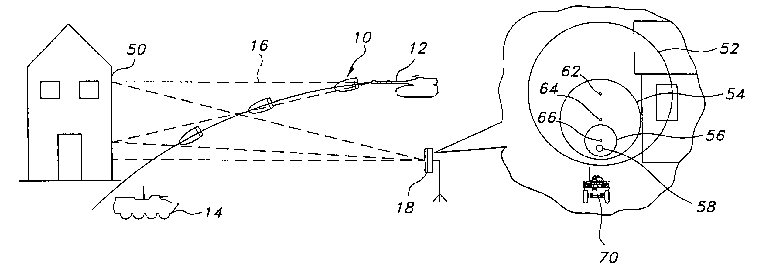
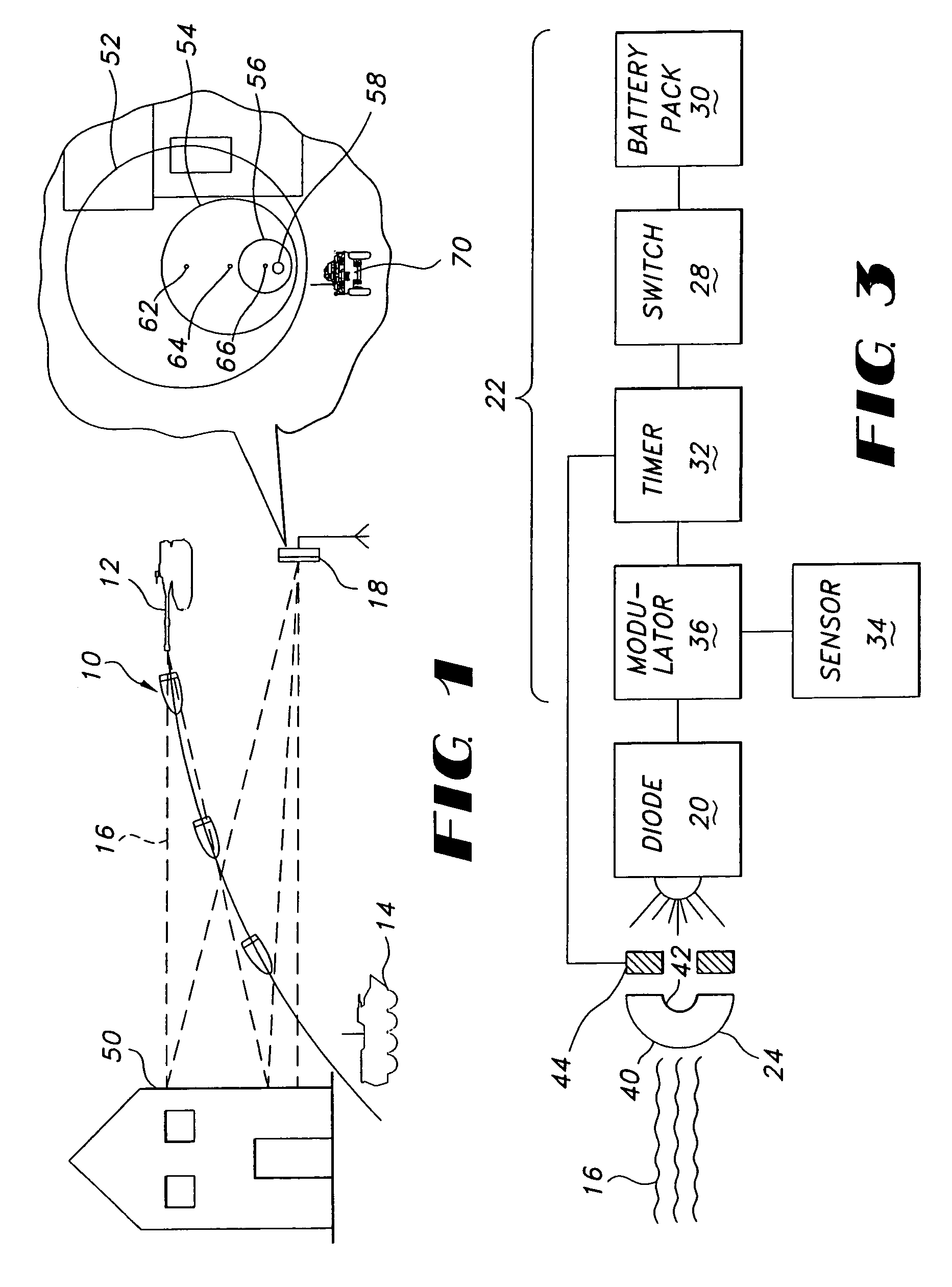
[0018]FIG. 1 schematically illustrates a tracer round 10 built following the teachings of the present invention. A gun 12 is shown having just fired the tracer round 10, and the round is shown in three successive positions as it travels toward (but misses) a target 14. A beam of coherent radiation 16 emitted by the tracer round 10 illuminates the target 14 and surrounding structures and is reflected to a receiver 18 so that the gunner may correct the aim point of the gun 12 for subsequent rounds.

[0019]The receiver 18 is shown as a separate antenna, but it is readily apparent that the receiver could as well be night vision goggles worn by the gunner or could be mounted to the same equipment or carriage to which the gun itself is mounted.

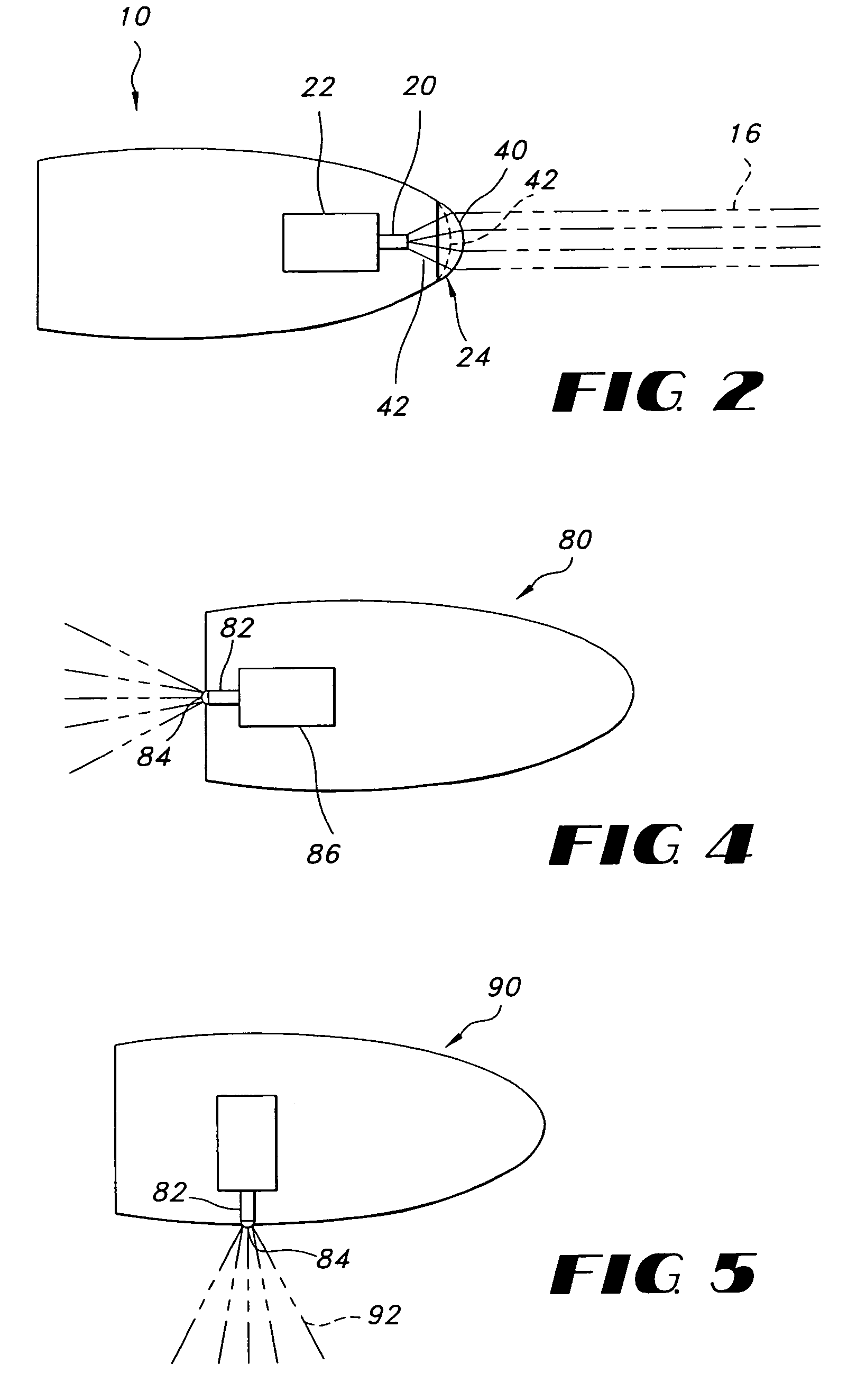
[0020]The tracer round 10 is illustrated schematically in FIG. 2. The round 10 includes a device 20 for emitting coherent electromagnetic radiation (a laser diode or similar device), an electronics and power supply package 22, and a lens or collimator...


PUM


Abstract

A covert tracer round has an infrared emitter of radiation mounted to its front, side or back. The radiation (which may be coherent or incoherent) is detected by a sensor that displays an image of the target and the beam. The sensor receives the beam directly if the emitter is on the back of the round and by reflection off the target or nearby objects if the emitter faces forward. The round may include a fixed or moveable collimating lens. The emitter may radiate radially from the round to signal troops or devices located along its path. The round may include sensors that gather significant information about chemicals or biological agents, about magnetic or gravitational anomalies or any other remotely detectable property and transmit that information to the sensor by modulating the emitted radiation.

Description

RELATED APPLICATION[0001]This application is a divisional of, and claims priority under 35 U.S.C. § 120 to, commonly-assigned U.S. application Ser. No. 10 / 241,669 which was filed on Sep. 11, 2002 now U.S. Pat. No. 6,880,467. The entire disclosure of this earlier application is hereby incorporated by reference.FIELD OF THE INVENTION[0002]The present invention relates to tracer rounds used by gunners to follow the trajectory of rounds as they are fired so as to aid the aim of subsequent rounds.BACKGROUND OF THE INVENTION[0003]Tracer rounds are used to help gunners follow the rounds shot to correct their aim when the rounds fall wide of their intended targets. Conventional tracer rounds give off a bright pyrotechnic light along the path from muzzle to impact. This has the unfortunate side effect of pointing directly at the gunner, making it easier for opposing forces to locate the source of fire.[0004]Some guns today are equipped with laser sights. These lasers project a dot on the tar...

Claims


Application Information

Patent Timeline
Patent Type & Authority Patents(United States)
IPC IPC(8): F41G3/00F41G1/00F42B12/36F42B12/38
CPCF42B12/382F42B12/36
Inventor KNAPP, DAVID JAMES
Owner RAYTHEON CO
Learn More