Water re-circulation valve

a water recirculation valve and valve body technology, applied in the field of valves, can solve the problems of small inconvenience, small amount of wasted water, and hot water that is fed into the water circulation branch to tend to cool, so as to improve prevent backflow. , the effect of enhancing the operation of the recirculation system

Inactive Publication Date: 2007-02-13
FAZEKAS DALE
View PDF2 Cites 12 Cited by
  • Summary
  • Abstract
  • Description
  • Claims
  • Application Information

AI Technical Summary

Benefits of technology

[0017]Also, in a preferred embodiment, a one-way valve is insertable in the upstream portion of the passageway that permits water to flow into the passageway from the piping upstream thereof, but prevents the flow of water out of the passageway.
[0019]One feature of the present invention is that the body portion is a unitary body, that is capable of containing a ball valve, a flow limiter valve, a one-way valve, and a pair of test ports. This feature has the advantage of providing the unitary structure for containing the primary flow components that are required for the device.
[0020]To further aid in servicing the invention, another feature of the present invention is that the flow limiter valve is removable from the body member. A flow limiter valve is preferably a cartridge type, that is inserted in the flow limiter valve port. A cap member is disposed on the end of the port to encase the flow limiter valve within the port. When servicing is required, the cap can be removed, to thereby enable the user to gain access to the flow limiter valve and remove it, and, if necessary replace it with a new flow limiter valve. Importantly, this service operation can be performed without the need for removing the body member.
[0021]A further feature of the present invention is that it includes a one-way valve that permits water within the particular riser in which the body member is disposed to only flow in an upstream-to-downstream direction, and which prevents back flow. By ensuring a one-way flow, the operation of the re-circulation system is enhanced by helping to better ensure that hot water is distributed equally among all of the branches, and that potentially relatively colder water that is contained within the return pipe of the re-circulation system does not flow backward into a riser, to thereby deliver relatively colder water to water outlets served by the particular riser.
[0022]The test ports help to enable the user to better evaluate the performance of the system, and diagnose problems within the re-circulation system. For example, a significant pressure drop across the flow limiter valve could be indicative of a situation wherein the flow limiter valve was clogged, and in need of replacing.

Problems solved by technology

One difficulty with such a one-way circulation system, especially when applied to hot water systems, is that over time, hot water that is fed into the water circulation branches will tend to cool.
In most residential dwellings, the wait for hot water presents only a minor inconvenience, as the size of most dwellings, and the concomitant volume of water within the pipes is small enough so that only a relatively small amount of water is wasted, and the wait is relatively short.
Although a single circulation system works well for most smaller buildings, certain situations exist wherein a one-way circulation system is highly undesirable.
One such situation involves larger buildings wherein the distance between the hot water heater and the outlets is large, and the volume of water in the circulation pipes is great.
This undesirable situation is exacerbated in large buildings with multiple water outlets, such as hotels and motels.
One difficulty with serving such a multi-branched re-circulation loop is that all of the branches may not be served evenly.

Method used


Image

  • Water re-circulation valve
  • Water re-circulation valve
  • Water re-circulation valve

Examples


Embodiment Construction

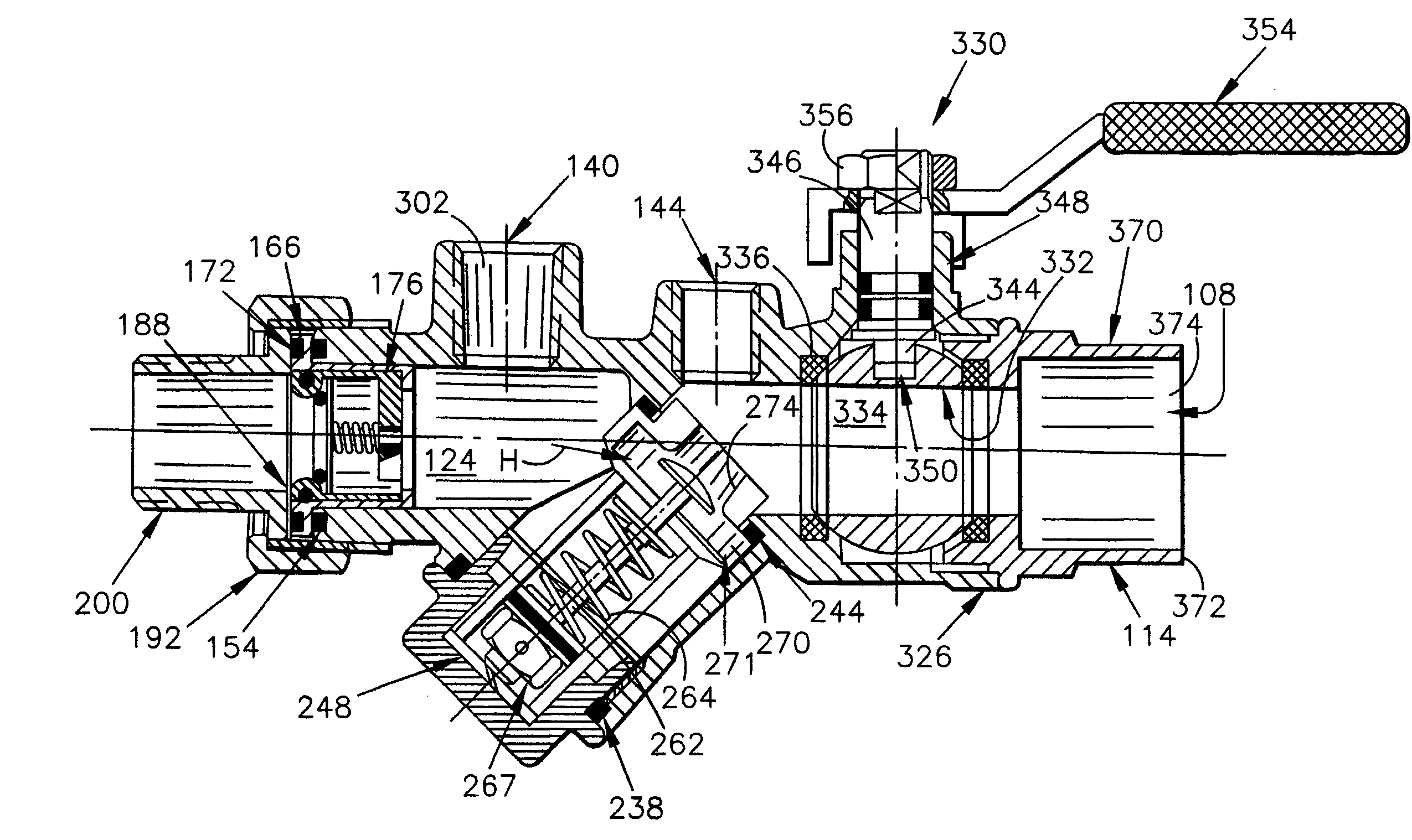
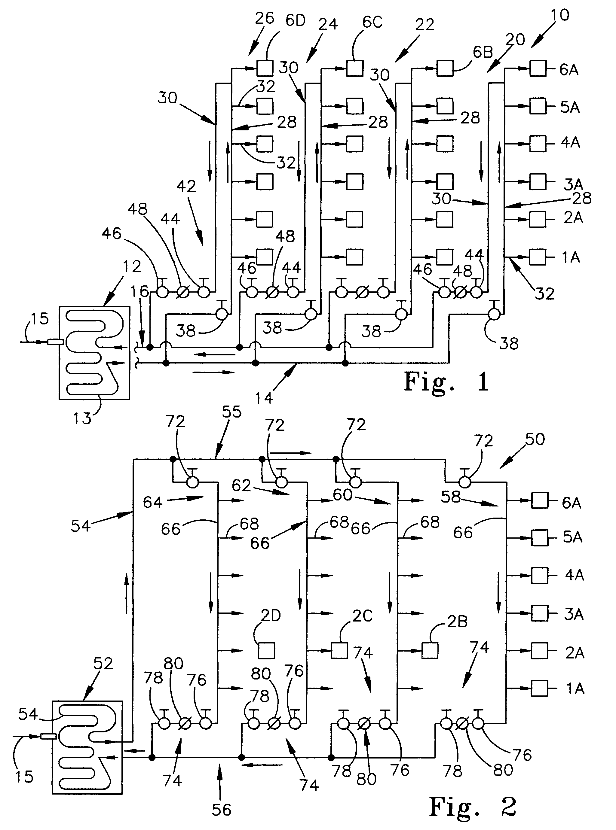
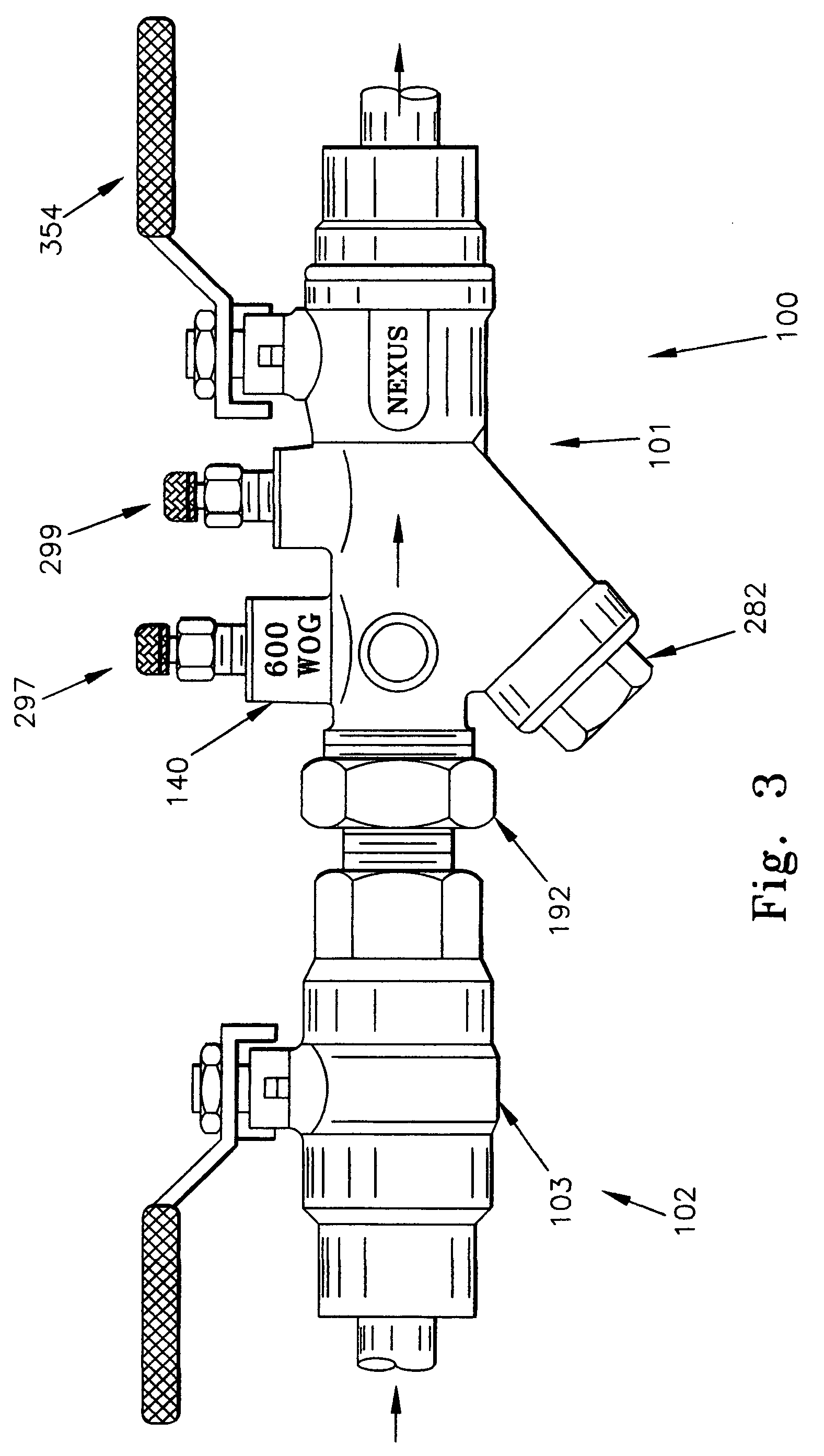
[0031]The valve 100 of the present invention is shown in FIGS. 3–5. However, before discussing the valve 100, it is first important to understand the environment in which it is used. To this end, an up-feed-type domestic hot water re-circulation system 10 is schematically shown in FIG. 1, and a down-feed-type domestic hot water re-circulation system is schematically shown in FIG. 2.

[0032]Turning first to FIG. 1, an up-feed-type domestic hot water system 10 includes a water heater 12, having a heating coil 13 disposed therein, for heating the water that flows through the heating coil 13. An outflow pipe 14 conducts water away from the water heater 12, and a return pipe 16 returns water to the water heater 12. The re-circulation system 10 re-circulates the water, so that the water 16 that flows through the risers of the re-circulation system 10 is directed into the return pipe 16 from which it is returned to coil 13, to be reheated, and then returned to outflow pipe 14. A fresh water ...


PUM


Abstract

A valve is provided for use in a domestic water re-circulation system The valve has a unitary body member that includes an upstream end and an upstream portion disposed adjacent to the upstream end. The body member also includes a downstream end and a downstream portion disposed adjacent to the downstream end; and a middle portion disposed between the upstream portion and the downstream portion. A radially outwardly facing outer wall and a radially upwardly facing inner wall exist. The radially inner facing wall defines an axially extending passageway extending between the upstream end and the downstream end, and through the upstream portion, middle portion and downstream portion of the body. The axially extending passageway includes a corresponding upstream end, a downstream end, an upstream portion, a middle portion and a downstream portion. The body further includes a radially extending controller port and a radially extending flow limiter port in fluid communication with the axially extending passageway.

Description

I. PRIORITY CLAIM AND TECHNICAL FIELD OF THE INVENTION[0001]The present application claims priority to U.S. Provisional application No. 60 / 523,954, that was filed on 24 Nov. 2003.[0002]The present invention relates to valves, and more particularly, to a valve for use in a water re-circulation system such as a heating or cooling system coil system or a domestic water system.II. BACKGROUND OF THE INVENTION[0003]Running water is an element of life that is taken for granted by persons who are fortunate enough to reside within the developed countries of the world. Most buildings include a system for delivering water from a water main to various points within the building having water outlets, from which the water can be drawn for use.[0004]Most residential and smaller buildings have a one-way water circulation system, wherein water is brought into the building from a nearby water main, and then directed by pipes to the various water outlets. For example, it is common within a single fami...

Claims


Application Information

Patent Timeline
Patent Type & Authority Patents(United States)
IPC IPC(8): F16K17/30F16K5/06F16K15/06
CPCF16K15/063F16K5/06F16K15/1848Y10T137/7842Y10T137/87917Y10T137/88054
Inventor FAZEKAS, DALE
Owner FAZEKAS DALE
Why Eureka
Try Eureka