
Electronic apparatus with connector of changeable attitude

a technology of electronic equipment and connectors, applied in the direction of coupling device connections, coupling contact member materials, coupling protective earth/shielding arrangements, etc., can solve the problems of solder cracking and usb connector of personal computers, and achieve the effect of improving the shockproof of the connector

Inactive Publication Date: 2007-02-13
FUJITSU LTD
View PDF20 Cites 17 Cited by
  • Summary
  • Abstract
  • Description
  • Claims
  • Application Information

AI Technical Summary

Benefits of technology

[0007]It is accordingly an object of the present invention to provide an electronic apparatus capable of improving shockproof of a connector.
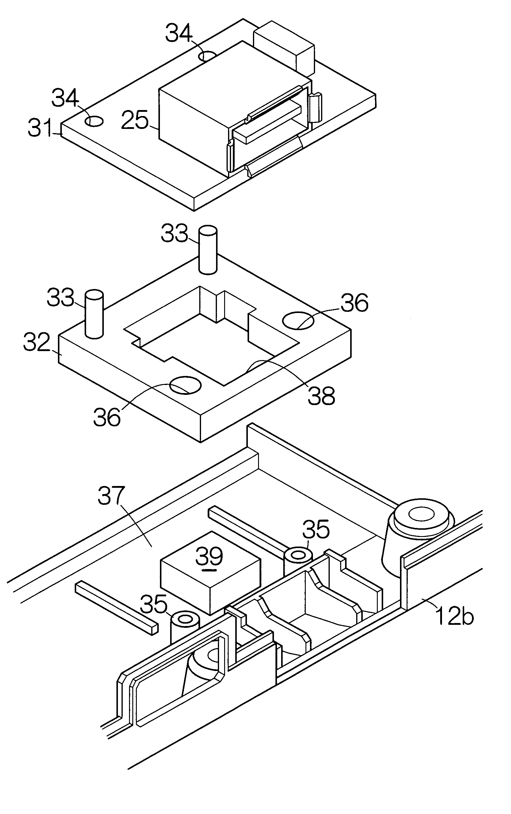
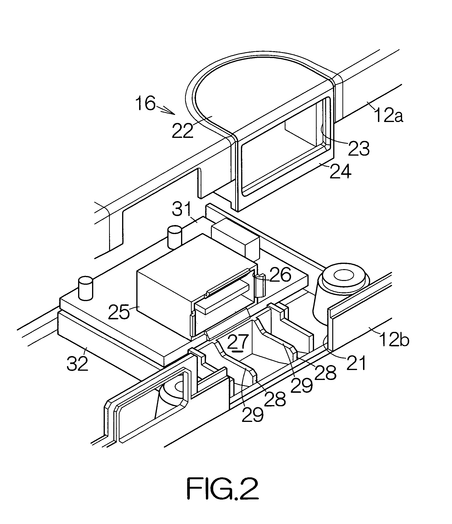
[0008]According to a first aspect of the present invention, there is provided an electronic apparatus comprising: an enclosure; a printed circuit board; a connector mounted on the printed circuit board; and a member interposed between the enclosure and the printed circuit board so as to hold the printed circuit board on the enclosure. The member allows change in the attitude of the printed circuit board relative to the enclosure.
[0009]When the connector is coupled to the other connector, the connector receives a force from the other connector in the electronic apparatus. The force induces change in the attitude of the connector and the printed circuit board. The change in the attitude in this manner enables consumption of the energy of the force within the member. Generation of stress can be suppressed in a bonding member such as solder that couples the connector with the printed circuit board, for example. Generation of cracks can be prevented in the solder. Shockproof is improved for the connector.
[0012]Otherwise, the electronic apparatus may further include: a first electrically conductive film formed on the back surface of the printed circuit board; a second electrically conductive film formed on the surface of the enclosure; and an electrically conductive elastic member interposed between the printed circuit board and the enclosure. The electrically conductive elastic member contacts the first and second electrically conductive films. Electric current is allowed to flow from the first electrically conductive film to the second electrically conductive film through the electrically conductive elastic member. The ground of the printed circuit board is in this manner reliably realized.

Problems solved by technology

Every time the security key is inserted and pulled off, the USB connector of the personal computer suffers from a force acting from the security key.
This movement may induce a crack in solder that couples the USB connector to the printed circuit board.

Method used


Image

  • Electronic apparatus with connector of changeable attitude
  • Electronic apparatus with connector of changeable attitude
  • Electronic apparatus with connector of changeable attitude

Examples


Embodiment Construction

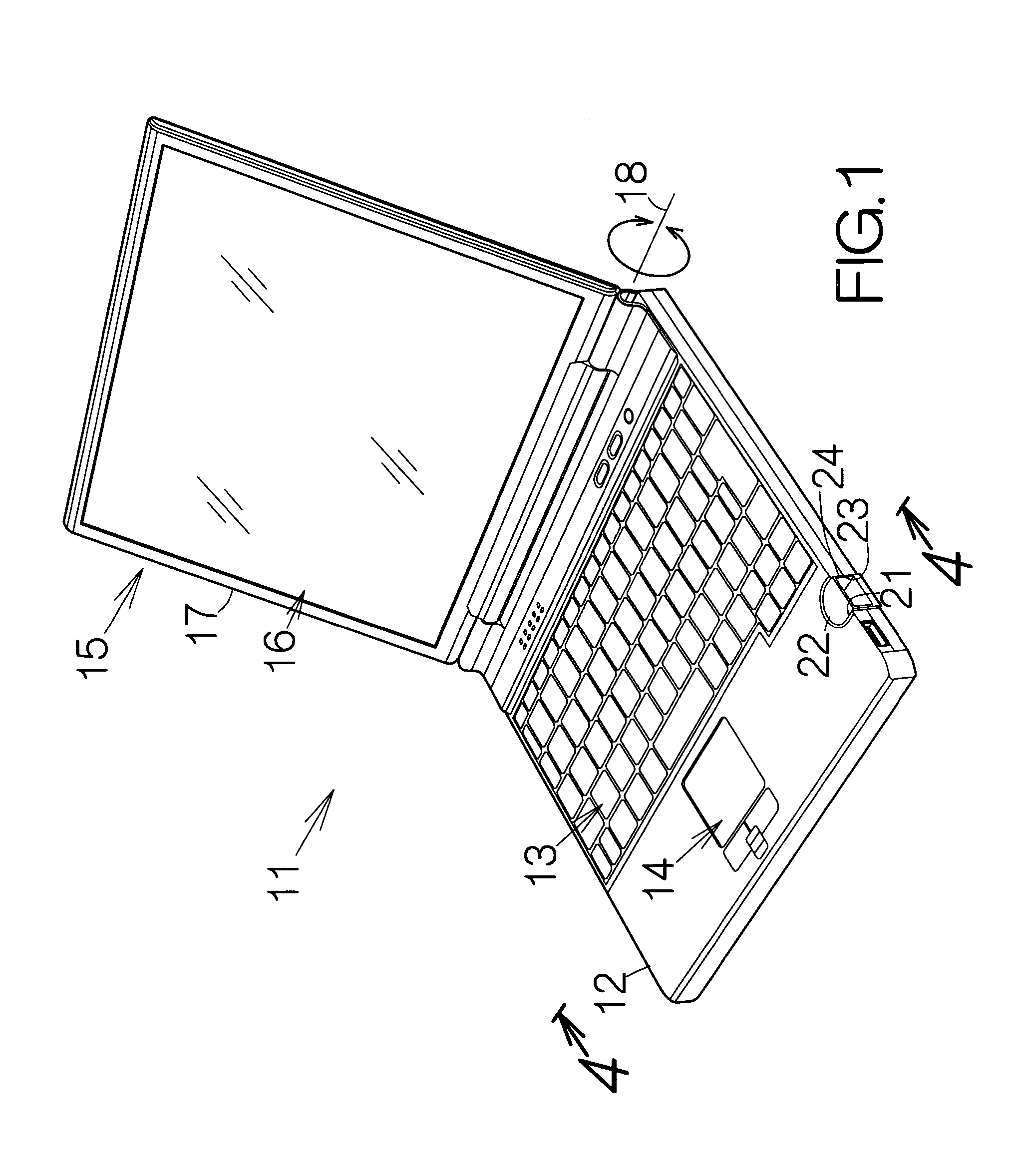
[0024]FIG. 1 schematically illustrates a notebook personal computer 11 as a specific example of an electronic apparatus according to an embodiment of the present invention. The notebook personal computer 11 includes a main body enclosure 12 containing a motherboard, for example. Electronic circuit elements such as a central processing unit (CPU), a memory unit, and the like, are mounted on the motherboard. The CPU is designed to execute various processings or calculations based on software programs and / or data temporarily stored in the memory, for example. The software programs and data may be stored in a mass storage such as a hard disk drive (HDD) enclosed within the main body enclosure 12.

[0025]Input devices such as a keyboard 13 as well as a pointing device 14 are incorporated in the main body enclosure 12. The user is allowed to input various instructions and data to the CPU through the input devices 13, 14. A so-called touch pad may be utilized as the pointing device 14, for e...


PUM


Abstract

A connector is mounted on a printed circuit board in an enclosure. A member is interposed between the enclosure and the printed circuit board so as to hold the printed circuit board on the enclosure. The member allows change in the attitude of the printed circuit board relative to the enclosure. When the connector is coupled to the other connector, the connector receives a force from the other connector in the electronic apparatus. The force induces the change in the attitude of the connector and the printed circuit board. The change in the attitude in this manner enables consumption of the energy of the force within the member. Generation of stress can be suppressed in a bonding member such as a solder coupling the connector with the printed circuit board, for example. Generation of cracks can be prevented in the solder. Shockproof is improved for the connector.

Description

BACKGROUND OF THE INVENTION[0001]1. Field of the Invention[0002]The present invention relates to a connector such as a Universal Serial Bus (USB) connector. In particular, the invention relates to an electronic apparatus including: an enclosure; a printed circuit board located on the enclosure within the enclosure; and a connector mounted on the printed circuit board.[0003]2. Description of the Prior Art[0004]A security key pursuant to the requirement of Universal Serial Bus (USB) is well known. When the security key is inserted into a USB connector of a personal computer, the boot of the personal computer is permitted. The security key is kept inserted during the operation of the personal computer. When the security key is withdrawn from the USB connector, the personal computer is locked. The locked personal computer will not accept any input.[0005]The security key is frequently inserted into and pulled off from the personal computer. Every time the security key is inserted and pul...

Claims


Application Information

Patent Timeline
Patent Type & Authority Patents(United States)
IPC IPC(8): H01R12/00
CPCH01R13/56H01R12/7011H01R2201/06
Inventor MIZUNO, YUSUKEKOBAYASHI, SONOMASAGOTO, KATSUICHI
Owner FUJITSU LTD
Learn More