Unlock instant, AI-driven research and patent intelligence for your innovation.

Hydraulically controllable constant speed drive and method for the design thereof

Inactive Publication Date: 2007-02-13
VAN DOORNES TRANSMISSIE BV
View PDF9 Cites 2 Cited by
  • Summary
  • Abstract
  • Description
  • Claims
  • Application Information

AI Technical Summary

Benefits of technology

[0004]It is an aim of the invention to provide for a CSD, wherein the disadvantageous effects of slip of the drive belt at start-up are mitigated in a reliable manner and at relatively low cost, so that the service life of the CSD is increased. The CSD according to the invention is provided with an input spring realizing a force that urges the pulley sheaves of the input pulley towards each other. In this manner it is advantageously achieved that at start-up the drive belt is clamped between the pulley sheaves of the input pulley, so that even initial rotation of the input shaft is transferred reliably through the drive belt to the generator unit. According to the invention, the axial force to be realized by the input spring to prevent slip of the drive belt, when the hydraulic pressure is still negligible, is surprisingly large. Mainly, because a torque load for overcoming the inertia of the drive belt, the output pulley, output shaft and a main load, i.e. the generator unit, and friction within the drive itself is relatively large, since the main load is directly connected to the drive. It was found that this is particular true in the aviation application of the CSD, where the drive is required to operate reliably in temperature range, including very low temperatures. At such low temperatures the viscosity of the hydraulic fluid used for control and lubrication of the drive is relatively high, adding to the friction within the drive, which needs to be overcome at start-up.

Problems solved by technology

This results in that in the event the control system fails to generate the hydraulic pressure, the rotational speed of the generator unit main shaft and, consequently, the frequency of the electrical current and voltage are also as low as possible.

Method used


Image

  • Hydraulically controllable constant speed drive and method for the design thereof
  • Hydraulically controllable constant speed drive and method for the design thereof
  • Hydraulically controllable constant speed drive and method for the design thereof

Examples


Embodiment Construction

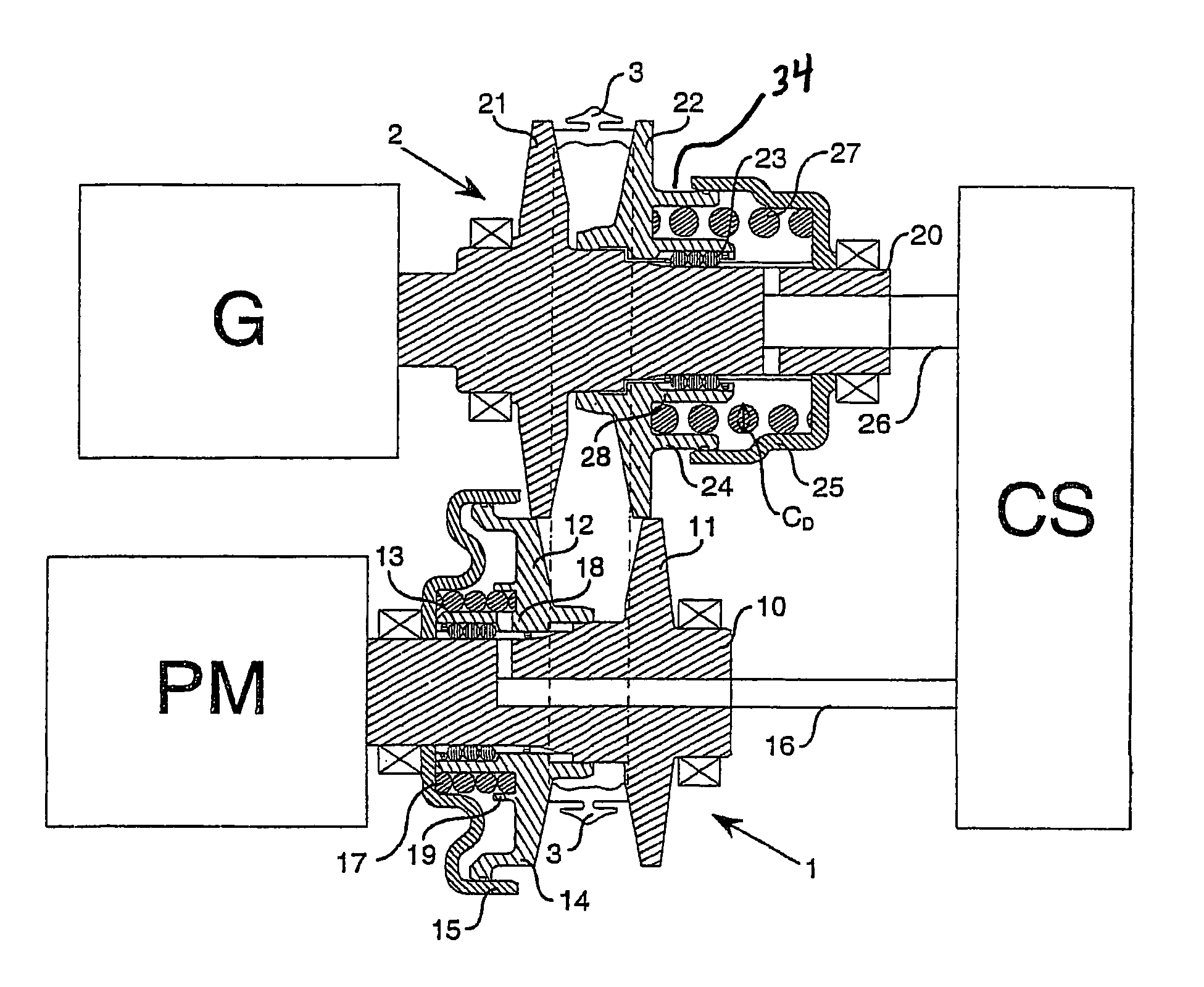
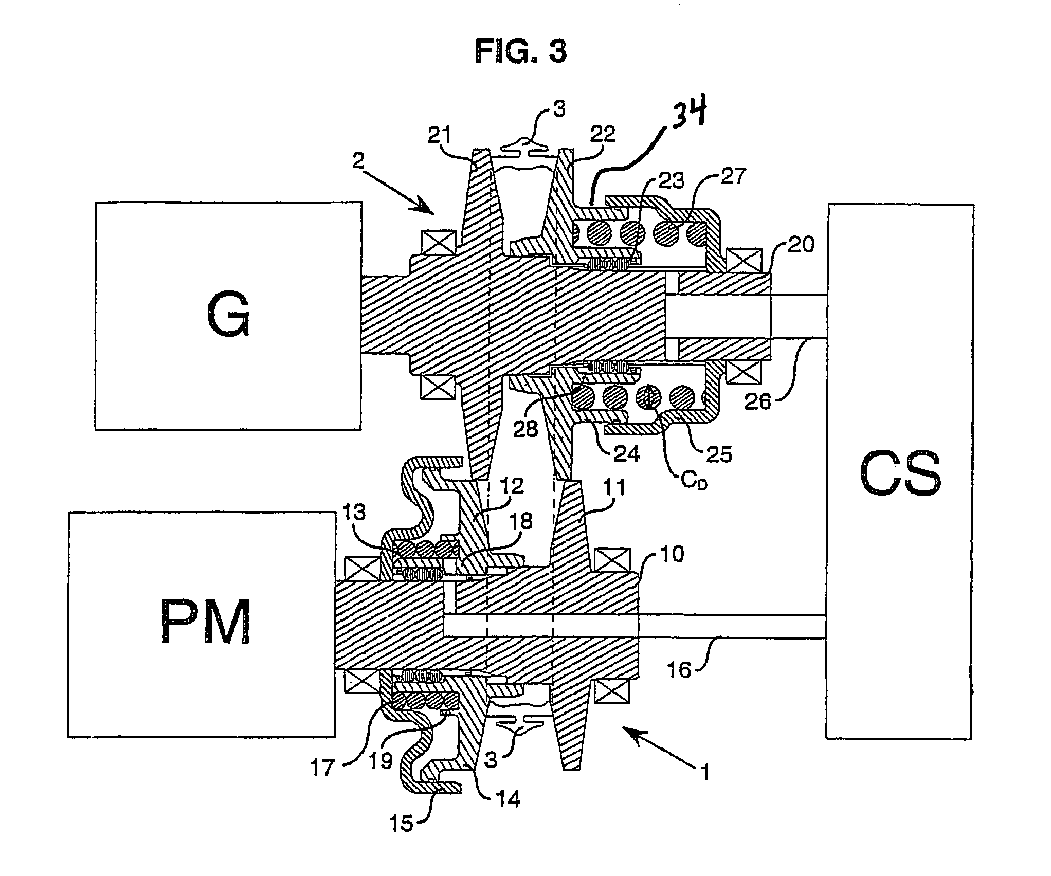
[0018]FIGS. 1 and 2 represent a hydraulically controllable constant speed drive, alternatively denoted as a CSD, according to the known art. The known CSD comprises an input shaft 10 to be drivably connected to a drive shaft of a prime mover PM and with an output shaft 20 to be drivingly connected to a main shaft of an electrical generator unit G. An input pulley 1 is provided on the input shaft 10 and an output pulley 2 is provided on the output shaft 20. Each pulley thereby comprising a pulley sheave 11; 21 that is fixed to the respective pulley shaft 10; 20 and a pulley sheave 12; 22 that is provided axially movable on the respective pulley shaft 10; 20, but fixed in a direction of rotation of the respective pulley shaft 10, 20 by means of a ball-spline 13; 23. For accommodation of the ball-spline 13; 23 and for countering a tendency to tilt with respect to the pulley shaft 10; 20, th movable pulley sheave 12, 22 is fitted on a sleeve 18, 28 of the pulley shaft 10; 20. Accordingl...


PUM


Abstract

A hydraulically controllable constant speed drive, includes an input shaft (10) provided with an input pulley (1), an output shaft (20) provided with an output pulley (2) and a drive belt (3). Each pulley (1; 2) is provided with two pulley sheaves (11, 12; 21, 22) that are mutually axially displaceable under the influence of a hydraulic pressure to be exerted in a piston-cylinder assembly (14, 15; 24, 25) associated with the pulley (1, 2) and that define a tapered groove of variable axial width wherein the drive belt (3) is accommodated. An input spring (17) is provided that realizes an axial force urging the pulley sheaves (11, 12) of the input pulley (1) towards each other to prevent slip of the drive belt (3) when the hydraulic pressure is negligible.

Description

BACKGROUND OF THE INVENTION[0001]The present invention relates to a hydraulically controllable constant speed drive, alternatively denoted as a CSD. Such a CSD is known from GB-A-2.220.038 and is particularly suited for use in a constant frequency generator for conversion of mechanical power into an electrical power, whereby a current frequency and voltage frequency of the electrical power is essentially constant, that is for example used in aviation.DESCRIPTION OF THE RELATED ART[0002]The known CSD comprises an input shaft to be drivably connected to a drive shaft of a prime mover and with an output shaft to be drivingly connected to a main load such as a main shaft of an electrical generator unit. An input pulley is provided on the input shaft and an output pulley is provided on the output shaft, whereby each pulley comprises two pulley sheaves that are mutually axially displaceable and that together define a tapered annular groove having a variable axial width. The CSD is further...

Claims


Application Information

Patent Timeline
IPC IPC(8): F16H55/49F16H61/662
CPCF16H61/66272
Inventor VAN SPIJK, JOHANNES GERARDUS LUDOVICUS MARIAPELDERS, HENDRIKUS ADRIANUS ARNOLDUS
Owner VAN DOORNES TRANSMISSIE BV
Features
  • R&D
  • Intellectual Property
  • Life Sciences
  • Materials
  • Tech Scout
  • Unparalleled Data Quality
  • Higher Quality Content
  • 60% Fewer Hallucinations
Learn More