Universal tibial augment

a tibial and universal technology, applied in the field of tibial augmentation, can solve the problems of ligamentous instability, failure of primary knee prostheses, bone loss on the proximal tibia, etc., and achieve the effect of greater economic benefits of the prosthetic knee system

Active Publication Date: 2007-02-13
DEPUY PROD INC
View PDF8 Cites 119 Cited by
  • Summary
  • Abstract
  • Description
  • Claims
  • Application Information

AI Technical Summary

Problems solved by technology

On occasion, the primary knee prostheses fails.
Failure can result from many causes, including wear, aseptic loosening, osteolysis, ligamentous instability, arthrofibrosis and patellofemoral complications.
In revision knee surgery or arthroplasty, bone loss on the proximal tibia can make it difficult to properly position and support the tibial component of the revision system on the proximal tibial surface.
The need for a large number of augments or wedges in the surgical systems of the prior art adds substantially to the cost of these systems.

Method used


Image

  • Universal tibial augment
  • Universal tibial augment
  • Universal tibial augment

Examples


Embodiment Construction

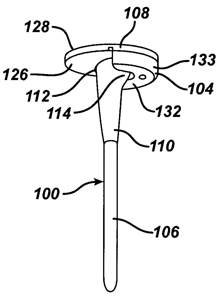
[0038]A prosthetic tibial system 10 incorporating the principles of the present invention is illustrated in FIGS. 10–16. The prosthetic tibial system 100 is a modular one, including a tibial component 102, a tibial augment 104 and a stem extension 106. It should be understood that the tibial system 100 will probably include multiple sizes of each of these components so that the surgeon can select the most appropriate size components for each patient.

[0039]As shown in FIGS. 10–11, the tibial component 102 includes a tibial tray 108 and an integral tibial stem 110. A pair of keels 112, 114 extend between and are integral with the tibial stem 110 and tibial tray 108. The stem extension 106 is provided for mounting into the intramedullary canal, as known in the art.

[0040]The tibial tray 108 has a central longitudinal plane 116 that divides the tray into symmetrical medial and lateral portions, designated 118 and 120 in FIG. 11. Each of the symmetrical portions 118, 120 has a closed-ende...


PUM


Abstract

A prosthetic knee system has a tibial component and a universal augment. A single augment can be used to support the tibial tray on either the medial or lateral side. The augment has reverse image sides and a through-bore with no threads. The tibial tray has a complementary threaded bore. The through-bore of the augment has a plane of symmetry perpendicular to its central longitudinal axis.

Description

[0001]This application claims the benefit of U.S. Provisional Application No. 60 / 409,319, entitled “Universal Tibial Augment”, filed on Sep. 9, 2002, by Deborah S. German and Jeffrey L. Koenemann, which is incorporated by reference herein in its entirety.BACKGROUND OF THE INVENTION[0002]The present invention relates generally to prosthetic joints and, more particularly, to a modular tibial augment for prosthetic knee joints. The tibial augment may be used to compensate for a broad range of types and sizes of bone deficiencies.[0003]The knee joint basically consists of the bone interface of the distal end of the femur and the proximal end of the tibia. Appearing to cover or at least partially protect this interface is the patella which is a sesamoid bone within the tendon of the long muscle (quadriceps) on the front of the thigh. This tendon inserts into the tibial tuberosity and the posterior surface of the patella is smooth and glides over the femur.[0004]The femur is configured wi...

Claims


Application Information

Patent Timeline
Patent Type & Authority Patents(United States)
IPC IPC(8): A61F2/38A61F2/00A61F2/30A61F2/46
CPCA61F2/30734A61F2/389A61F2310/00029A61F2002/30131A61F2002/30433A61F2002/30604A61F2002/30616A61F2002/3069A61F2002/30708A61F2002/30736A61F2002/30774A61F2002/30794A61F2002/30805A61F2002/30878A61F2002/30884A61F2002/30892A61F2002/30894A61F2002/4631A61F2220/0041A61F2230/0013A61F2250/0084A61F2002/3079
Inventor GERMAN, DEBORAH S.KOENNEMAN, JEFFREY L.
Owner DEPUY PROD INC
Why Eureka
Try Eureka