DC voltage converter and method for converting a DC voltage

a voltage converter and dc technology, applied in the direction of electric variable regulation, process and machine control, instruments, etc., can solve the problem of unsatisfactory crossover influence (also referred to as crosstalk) between the various outputs, and achieve the effect of reducing nois

Active Publication Date: 2007-02-13
INFINEON TECH AG
View PDF10 Cites 28 Cited by
  • Summary
  • Abstract
  • Description
  • Claims
  • Application Information

AI Technical Summary

Benefits of technology

[0020]Cyclically rotating the channels means that the error of the first channel is used for regulation in a first interval of time, the error of the second output channel is used in a second interval etc. This ensures that each channel is subjected to regulation, albeit in succession. This, in turn, ensures that the invention also reliably adjusts the outputs of the DC voltage converter to constant potential values when no electrical load is connected to the first output.
[0022]The control loop may comprise an analog / digital converter, which is connected upstream of the regulator and thus connects the first output to the regulator. This makes it possible to design the regulator as a digital module by implementing, for example, a digital pulse width modulation principle.
[0025]The energy store may comprise a common coil, with the result that the circuit can be produced in integrated fashion in a particularly cost-effective manner by integrating only one coil.
[0038]In yet another embodiment of the method for converting DC voltage, that output which has the widest pulse width at the time is always selected as a reference variable for the control loop. As a result, even fewer changeover operations are required. This, in turn, results in the noise being reduced in the output voltages.

Problems solved by technology

The problem with known step-up converters having a plurality of outputs is that there may be undesirable crossover influence (also referred to as crosstalk) between the various outputs.

Method used


Image

  • DC voltage converter and method for converting a DC voltage
  • DC voltage converter and method for converting a DC voltage
  • DC voltage converter and method for converting a DC voltage

Examples


Embodiment Construction

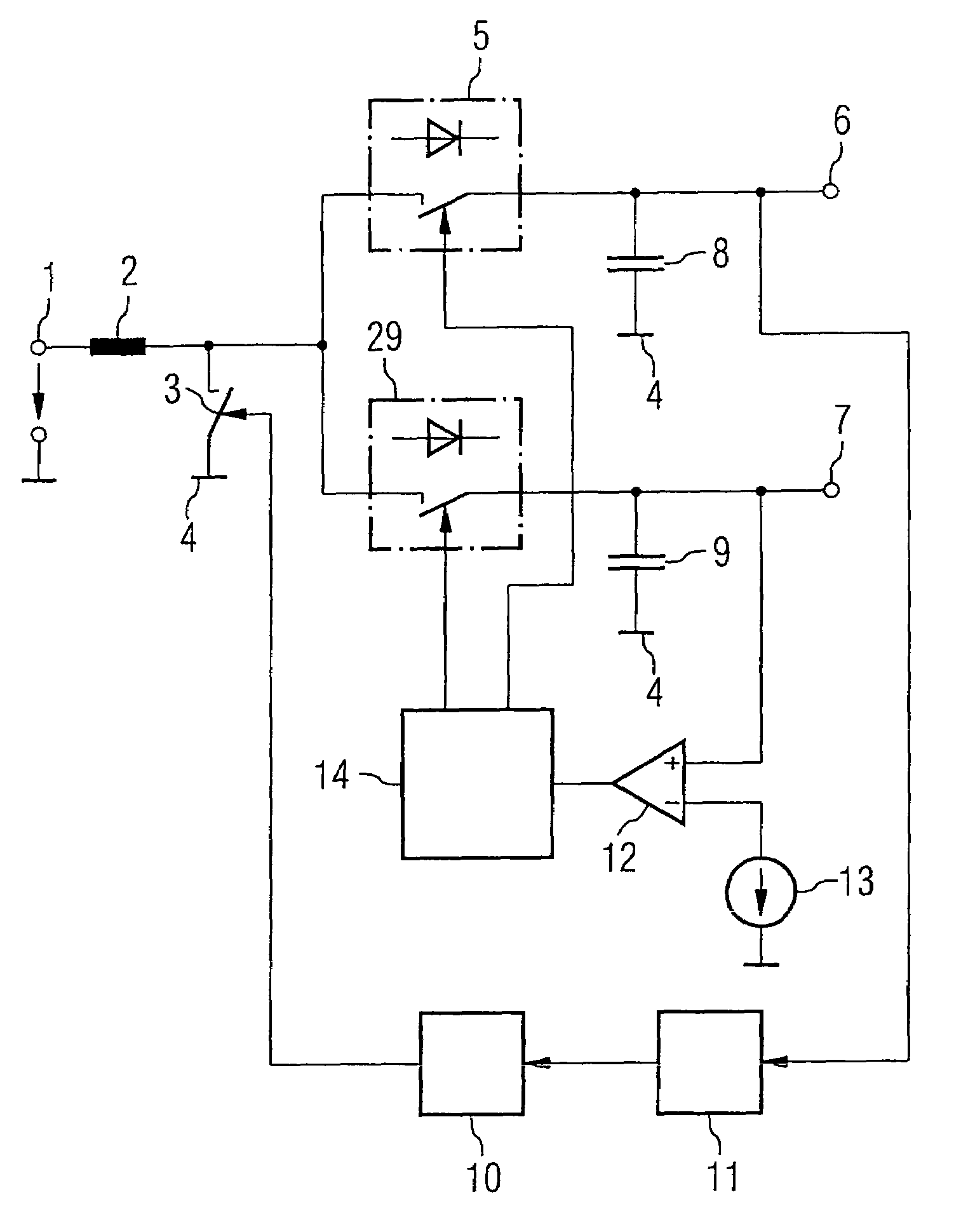
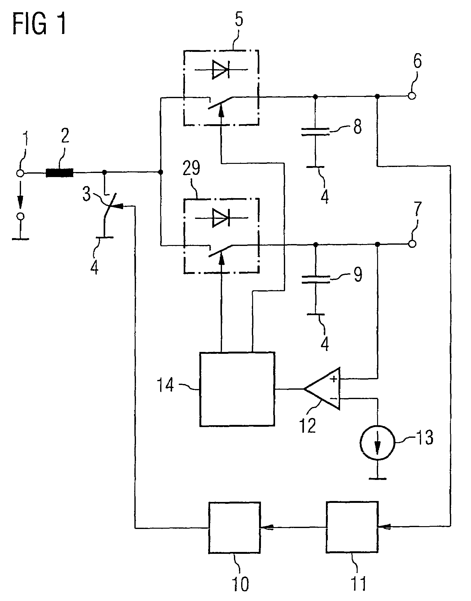
[0045]FIG. 1 shows a DC voltage converter, which is suited to converting a DC voltage that is applied on the input side into two different output DC voltages. In this case, an input 1 for supplying a DC voltage is provided, an energy store 2 in the form of a coil being connected to the input. The free terminal of the energy store 2 is connected to a reference potential terminal 4 via a switch 3. The circuit node that is formed between the energy store 2 and the switch 3 is furthermore connected to a first output 6 via a first means for influencing the voltage magnitude 5 and to a second output 7 via a second means for influencing the voltage magnitude 29. The first and second outputs 6, 7 are each designed to provide an output voltage in the form of a DC voltage. The first and second outputs 6, 7 are connected to the reference potential terminal 4 via a respective charge store 8, 9 that is in the form of a capacitor. The switches 5, 29 have a diode function in order to make it possi...


PUM


Abstract

A DC voltage converter and a method for converting a DC voltage into a plurality of output-side DC voltages are disclosed. A reference variable for a control loop is provided at one output, while a respective threshold value comparison is carried out at the other outputs. An energy store at the input of the DC voltage converter can be changed over to different output branches in a manner dependent on the threshold value comparison. The energy store is driven using the control loop. The proposed principle makes it possible, with a high degree of efficiency, to provide various DC voltages with little crossover influence between the outputs and, at the same time, with constant output voltages.

Description

REFERENCE TO RELATED APPLICATIONS[0001]This application claims the benefit of the priority date of German application DE 10 2004 031 393.8, filed on Jun. 29, 2004, the contents of which are herein incorporated by reference in its entirety.FIELD OF THE INVENTION[0002]The present invention relates to a DC voltage converter having a plurality of outputs and to a method for converting a DC voltage into a plurality of output-side DC voltages.BACKGROUND OF THE INVENTION[0003]DC voltage converters having a plurality of outputs are also referred to as multichannel DC voltage converters.[0004]DC voltage converters of this type convert a DC voltage that is applied on the input side into a plurality of output DC voltages which are usually different.[0005]DC voltage converters are used, for example, in integrated circuits in order to provide a plurality of different supply voltages for function blocks of the integrated circuit. In this case, it is particularly important for the output DC voltag...

Claims


Application Information

Patent Timeline
Patent Type & Authority Patents(United States)
IPC IPC(8): G05F1/40
CPCH02M3/158H02M2001/009H02M1/009
Inventor KRANZ, CHRISTIAN
Owner INFINEON TECH AG
Why Eureka
Try Eureka