Presentation system, material presenting device, and photographing device for presentation

a technology of presentation system and presenting device, which is applied in the field of presentation system and material (document) presenting device, and the use of photographing device for presentation, can solve the problems of unstable point, indirect pointing operation, and erroneous projection of laser beams to be hazardously incident on the eyes of the audience, so as to achieve the effect of effective use of light and swift switching

Inactive Publication Date: 2007-02-13
FUJI PHOTO OPTICAL CO LTD
View PDF20 Cites 50 Cited by
  • Summary
  • Abstract
  • Description
  • Claims
  • Application Information

AI Technical Summary

Benefits of technology

[0052]According to the present invention, the photographing device for presentation is switched between using the image photographed by the photographing device provided in the path for normal photographing and the image photographed by the photographing device for photographing light of a specific wavelength, whereby the photographing device for presentation can be swiftly switched between normal photographing and specific wavelength light photographing. Therefore, the invention does not require switching operation for the optical filter which is removably positioned in the optical path so as to switch between normal photographing and specific wavelength light photographing. In addition, since the device for removably placing in an optical filter is not needed, the structure of the photographing device can be designed simply.
[0053]An optical filter which can allow light to pass therethrough of a specific wavelength may be provided in the photographing optical path for photographing light of a specific wavelength so as to form a photographing optical path for specific wavelength light photographing. In addition, the photographing optical path extending from the object to the photographing optical path may be divided into a path for normal photographing and a path for photographing light of a specific wavelength by a beam splitter which may be for dividing light into a light component of a specific wavelength and another light component. In this case, an optical filter may not be needed, whereby the structure of the photographing device may be designed more simply, and light can be effectively used. The specific wavelength light of the present invention may be infrared light.

Problems solved by technology

Shaking greatly and adversely influences the pointing operation, thereby making the point unstable.
Also the laser beam may be erroneously projected to be hazardously incident on the eyes of the audience.
In the improved technique described above, however, the pointing operation is indirect.
Due to this, it is difficult to indicate the point swiftly, and it is insufficient to suppress shaking.
However, the method of indicating a part by directly touching the material causes a problem as described below.
Due to this, the material presenting device is caused to be larger, and new problems, such as storing the device, thereby occur.
With this structure, however, the harness of the camera may be twisted and broken.
In addition, the material presenting device may be large since the oscillating mechanism for tilting the body of the camera is complicated.
Therefore, the manufacture of the device incurs high cost, and it is difficult for the operator to understand the operating method thereof, whereby the operator may easily make mistakes in the operation.
In addition, the manufacturing cost is increased since the touch panel is expensive.
Various safe pointing systems have been proposed, instead of one using a laser pointer, because a laser beam may be erroneously projected to be hazardously incident on the eyes of the audience.
The operation of the optical filter is troublesome if the operation is performed by hand.
The structure of the device is complicated if a driving mechanism is provided and, moreover, the operation is electrically-driven under remote control.
In addition, in both cases, the operation is time consuming, and ease of use of the system is not satisfactory.

Method used


Image

  • Presentation system, material presenting device, and photographing device for presentation
  • Presentation system, material presenting device, and photographing device for presentation
  • Presentation system, material presenting device, and photographing device for presentation

Examples


first embodiment

(1) First Embodiment

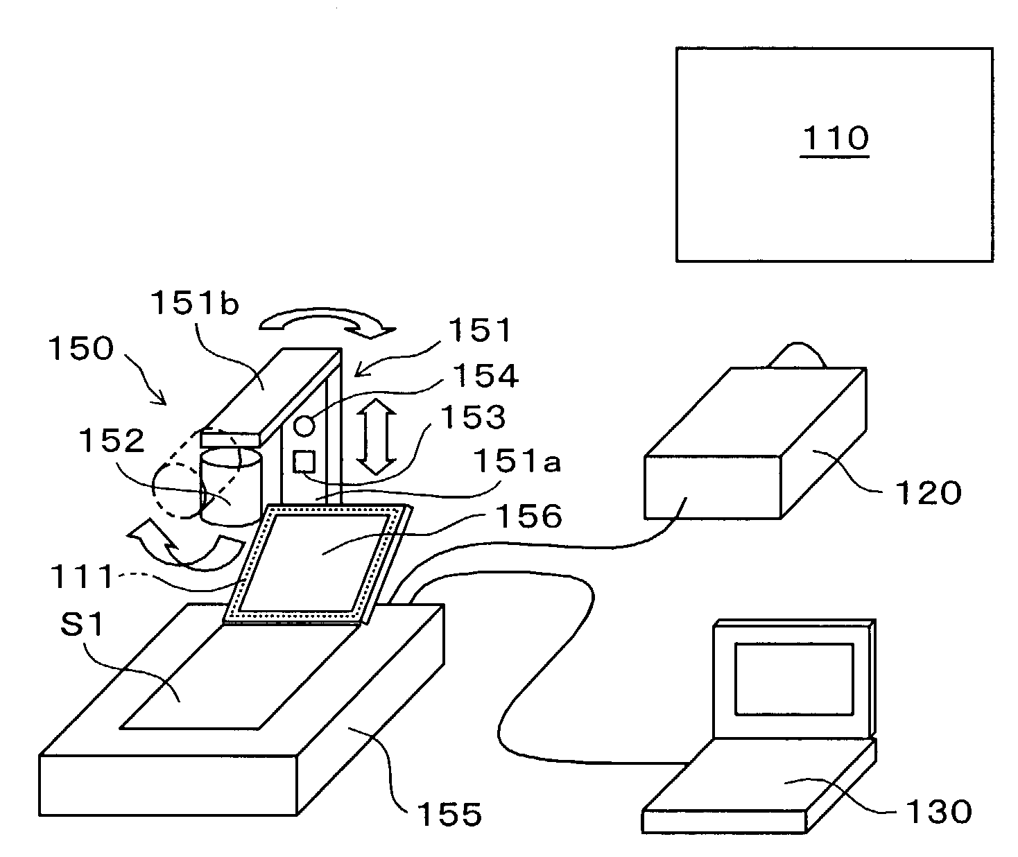
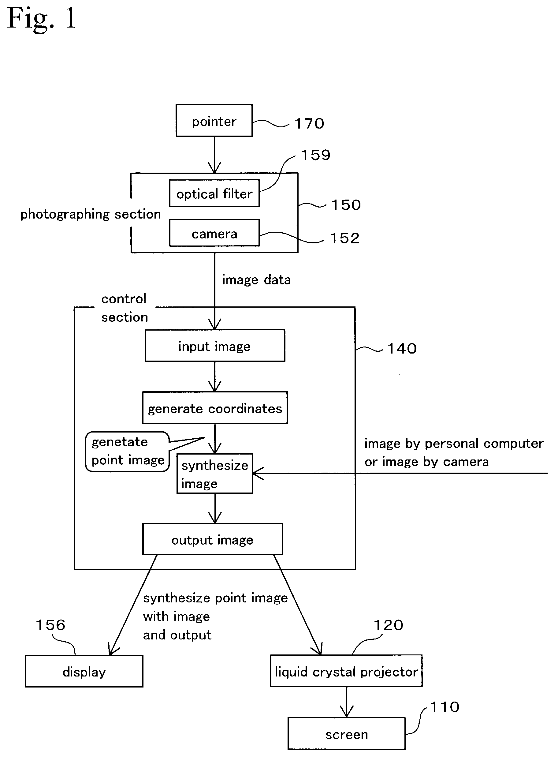
[0100]FIG. 1 systematically shows a configuration and a function of a presentation system in a first embodiment according to the present invention. FIG. 2A shows one arrangement of the configuration of the system schematically. As shown in the figures, the system comprises a screen (displaying device) 110, a liquid crystal projector 120, a personal computer 130 of a note type, a control section (control device) 140 and a photographing section 150.

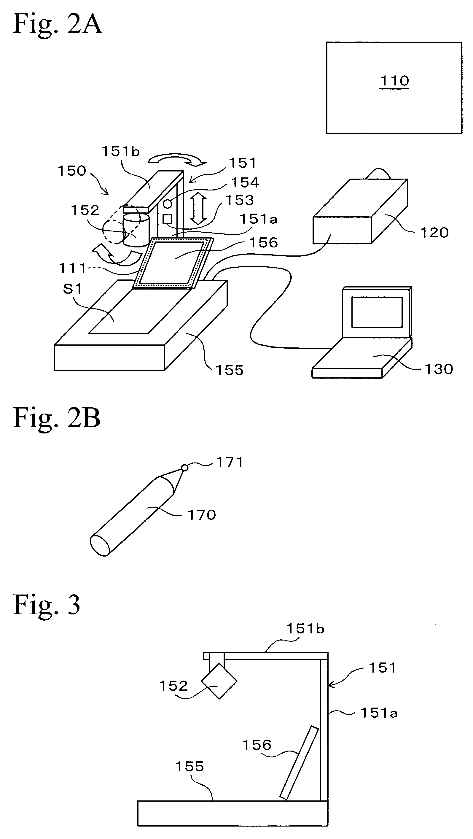
[0101]The photographing section 150 comprises a document photographing apparatus. As shown in FIG. 2A and FIG. 3, the document photographing apparatus is equipped with a manuscript pedestal 155, a camera (photographing device) 152 supported by the manuscript pedestal 155 via an arm 151, and a display 156. The arm 151 has an inverted L-shape composed of a vertical portion 151 a extending vertically and a horizontal portion 151b at the upper end of the vertical portion 151a. The horizontal portion 151b extends forward of a...

second embodiment

(2) Second Embodiment

[0137]FIG. 15 is a diagram showing a configuration and a function of a presentation system in a second embodiment according to the present invention. FIG. 16 shows the concrete image of the system including a material presenting device 201 in the second embodiment according to the present invention.

(1) Schema of the System

[0138]The configuration and the function of the presentation system are described below, with reference to FIG. 15.

[0139]In the system, image data related to three kinds of images, that is, an image photographed by a photographing section 202, an external image generated by a personal computer, and an image stored by a memory device 204 are switched to one of them by a switching device 205, and stored in a frame memory 206. The image data is input into an image outputting section 208 through an image synthesizing section 207, and is input into an image displaying device such as a screen and a display, whereby an image corresponding to the image...

third embodiment

(3) Third Embodiment

[0167]FIG. 23 shows schematically the entire presentation system equipped with a material presenting device in the third embodiment according to the present invention. In FIG. 23, numeral symbol 301 denotes a screen, 302 denotes a liquid crystal projector which projects a liquid crystal image onto the screen 301, 303 denotes a control arithmetic operation section (control device), and 304 denotes a personal computer. Image data on the display of the personal computer is output to the liquid crystal projector 302, and is projected from the liquid crystal projector 302 to the screen 301.

[0168]In FIG. 23, numeral symbol 305 denotes a material presenting device. In FIG. 24, this material presenting device 305 is equipped with a material mounting pedestal 351 (material mounting device) which is set to be a base of the material presenting device. The control arithmetic operation section 303 is provided in the inside of the material mounting pedestal 351 and is connecte...


PUM


Abstract

A presentation system comprises a display for setting a virtual screen, a pointing mark for operating a point on the display, a photographing device for photographing the pointing mark and the display, a displaying device for displaying a predetermined image or the photographed image photographed by the photographing device, and a control device. The control device calculates coordinates of the pointing mark on coordinates of the virtual screen and has a pointing function for synthesizing a predetermined point image at coordinates of the image on the displaying device, which correspond to the coordinates of the pointing mark.

Description

BACKGROUND OF THE INVENTION[0001]1. Field of the Invention[0002]The present invention relates to a presentation system, a material (document) presenting device, and a photographing device for presentation.[0003]2. Description of the Related Art[0004]In a presentation, reference images may be displayed to an audience by displaying documents photographed by a document photographing apparatus on a screen, by reflecting a display of a personal computer on a screen, and by other methods. A laser pointer which indicates a point on the image on the screen by projecting a laser beam is often used. A laser pointer of this type has, however, the following disadvantages. Shaking greatly and adversely influences the pointing operation, thereby making the point unstable. Also the laser beam may be erroneously projected to be hazardously incident on the eyes of the audience. To overcome these disadvantages, the applicant proposed, in Japanese Patent Unexamined Application Publication No. 2001-299...

Claims


Application Information

Patent Timeline
Patent Type & Authority Patents(United States)
IPC IPC(8): G09G5/00G06F3/038G06F3/042G09G5/08
CPCG06F3/0304G06F3/0425G06F3/0386G09G5/08G06F3/03545
Inventor NISHIMURA, MITSUYOSHIYOKOYAMA, JUNICHINAGASHIMA, TAKASHI
Owner FUJI PHOTO OPTICAL CO LTD
Why Eureka
Try Eureka