Lens array for image sensor and image-scanning device incorporating the lens array

a technology of image sensor and lens array, which is applied in the field of lens array for image sensor and imagescanning device incorporating the lens array, can solve the problems of low self-shape retention, frame cannot be molded with a high degree of accuracy, and it is difficult to install the rod lens array without inclination, so as to prevent the amount of light level

Active Publication Date: 2007-02-13
NIPPON SHEET GLASS CO LTD
View PDF4 Cites 12 Cited by
  • Summary
  • Abstract
  • Description
  • Claims
  • Application Information

AI Technical Summary

Benefits of technology

[0018]In this manner, by using the lens plate with lenses formed in many rows even in a sub-scanning direction, deterioration of an amount of light level resulting from the displacement (Δy) between the light axis and the line image sensor can be eliminated.
[0020]Further, by setting an angle of aperture of a single lens of the lens array between 4 and 10 degrees, it is possible to satisfy both an amount of light transmitted and a depth of focus.
[0021]The present invention also includes an image-scanning device in which the lens array for an image sensor, an illuminating device, and a light-receiving element are incorporated in a frame. In particular, the illuminating device of the image-scanning device is provided with a light guide which reflects the light incident from an end face on the inner surface and causes the light to be emitted from a light-emitting surface provided along the longitudinal direction. The light guide is provided with two kinds of reflective curved surfaces and the collecting position of the light reflected by each curved surface differs. In this manner, it is possible to effectively prevent the deterioration of the amount of light level resulting from the elevation of a document.
[0022]A cross-sectional shape of the two kinds of reflective curved surfaces in the direction perpendicular to the longitudinal direction of the light guide is considered to be an oval arc or a parabola. In the case where a pair of right and left illuminating devices is incorporated in the image-scanning device, it is possible to exhibit the same effect as above by changing the height of each illuminating device.

Problems solved by technology

Thus, the frame cannot be molded with a high degree of accuracy and its self-shape retention is also low.
In this manner, it is difficult to install the rod lens array without inclination and as shown in FIG. 10, the displacement (Δy) is produced between the light axis of the rod lens array and the line image sensor.
In this manner, if deterioration of the amount of light level takes place, deformation in line is caused to lower the image quality when, for example, a linear image such as a ruled line is scanned.
However, since the production cost becomes high even in rod lens array in one row, to have the rod lens array disposed in two rows makes the production yield worse to increase the cost.
Further, even though the rod lenses are provided in two rows, it is not possible to completely eliminate the displacement of light axis.
On the other hand, if a micro lens array is employed, it is easy to have the lens disposed in many rows, but in the case of an ordinary micro lens array, it is not possible to provide an erect 1:1 imaging lens.
Further, in the case of the contact-type image-scanning device, there is also a problem of the deterioration in resolution resulting from the elevation of a document as well as the displacement between the light axis of the rod lens array and the line image sensor.
In the conventional image-scanning device, since the irradiated light from an illuminating device is designed to be concentrated substantially on the glass plate (the document desk), the amount of light irradiated becomes uneven at a portion where the document is elevated to cause the resolution to deteriorate.
Further, even though the amount of light irradiated is dispersed to a certain degree in accordance with the elevation of the document, there is still a problem of focal depth.
Thus, an insufficient amount of light results.

Method used


Image

  • Lens array for image sensor and image-scanning device incorporating the lens array
  • Lens array for image sensor and image-scanning device incorporating the lens array
  • Lens array for image sensor and image-scanning device incorporating the lens array

Examples


Embodiment Construction

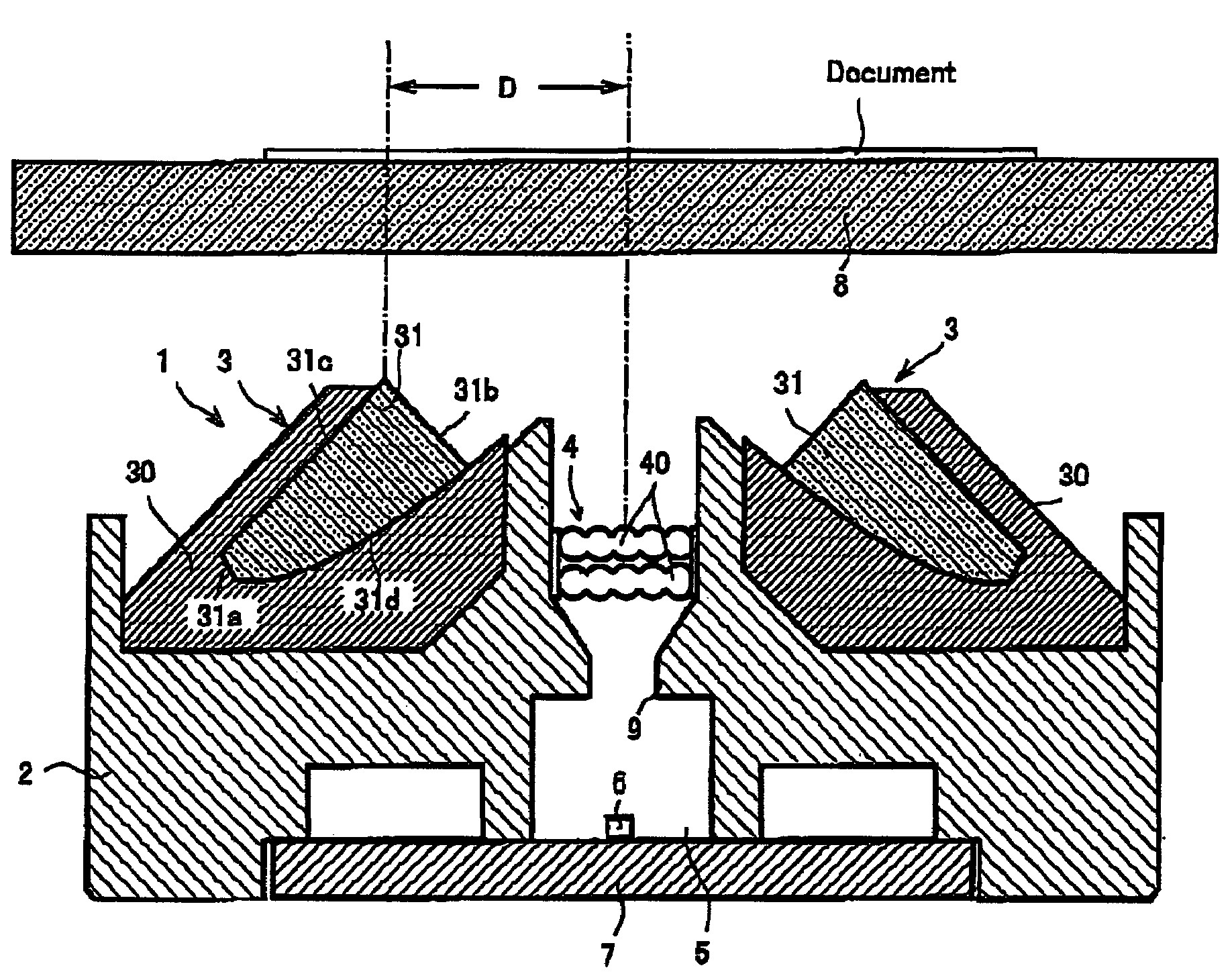
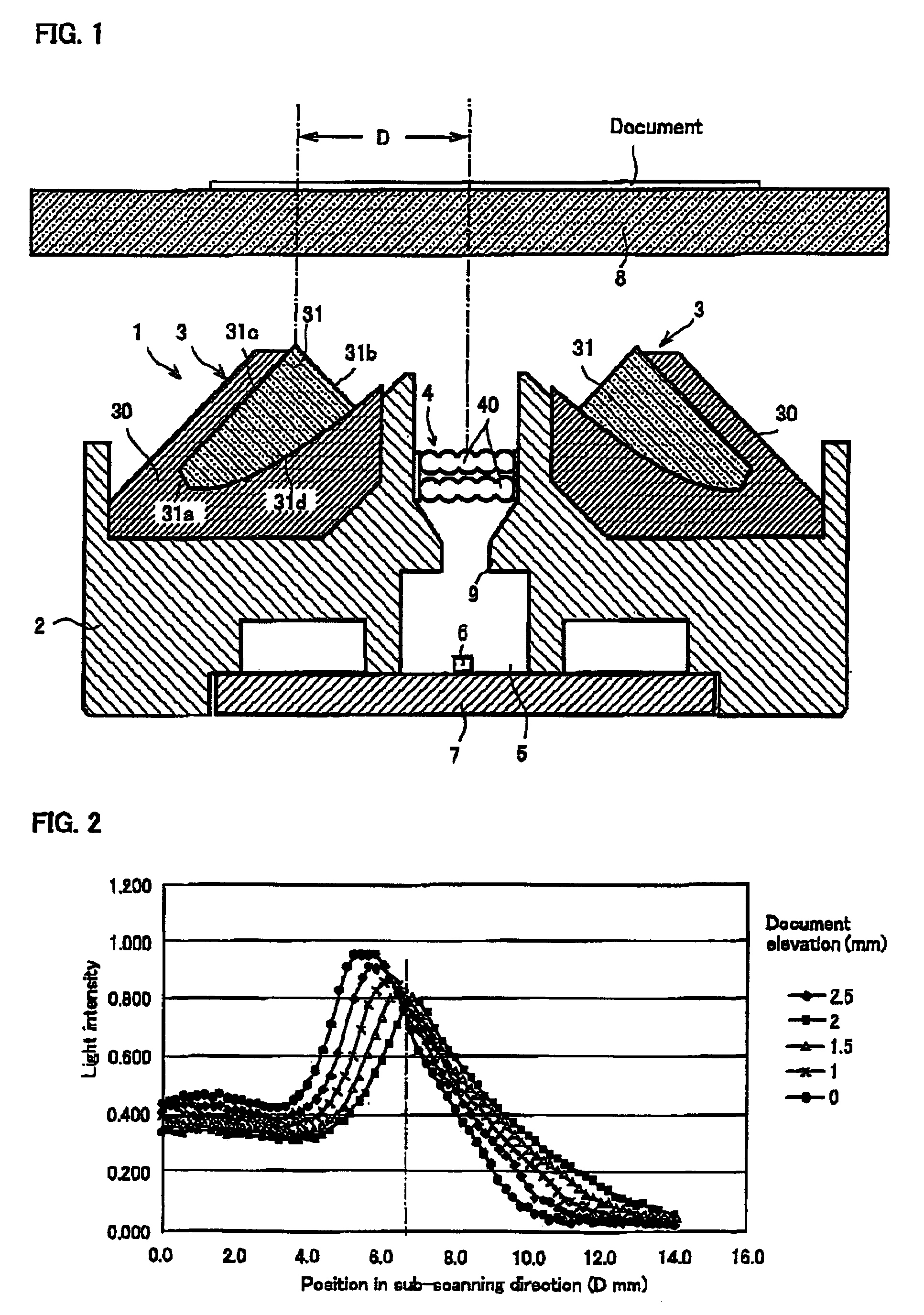
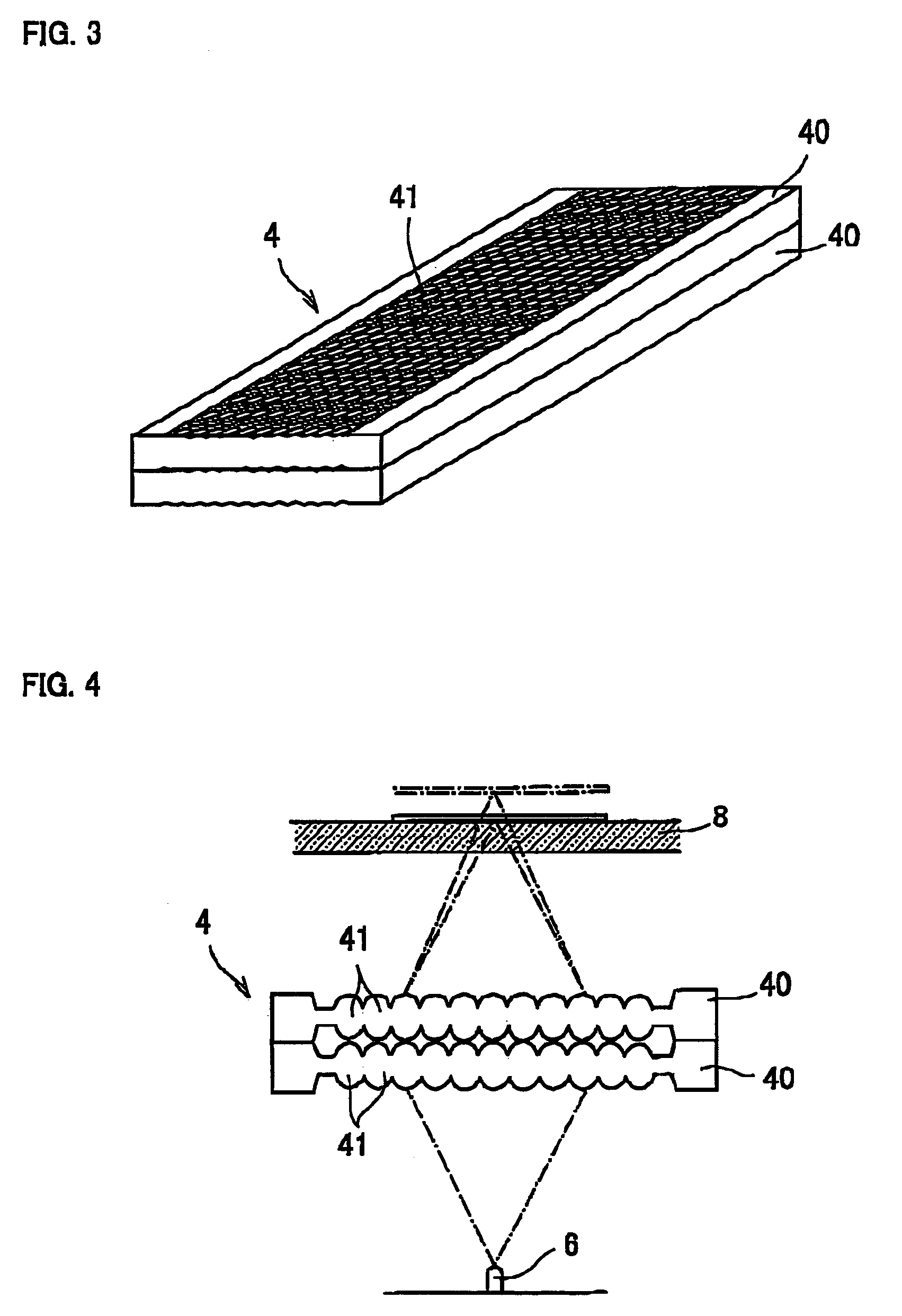
[0037]Preferred embodiments of the present invention will now be described with reference to the accompanying drawings. FIG. 1 is a cross-sectional view of an image-scanning device in which a lens array according to the present invention is incorporated. FIG. 2 is a perspective view of the lens array according to the present invention. FIG. 3 is a graph showing the relationship between a position in a sub-scanning direction and the intensity of light for each amount of elevation of a document surface. FIG. 4 is a view explaining the image formation by the lens array according to the present invention.

[0038]An image-scanning device 1 is transversely provided with line-illuminating devices 3 and 3 within a frame 2 and a lens array 4 is disposed between these line-illuminating devices 3 and 3. Formed at the lower part of the frame 2 is a depressed section 5 on which a base plate 7 to which an image sensor (i.e., a light-receiving element) 6 is secured is mounted. A glass plate 8 on whi...


PUM


Abstract

A lens array 4 is formed as an erect 1:1 imaging lens by superimposing two lens plates 40 and 40 together. Each lens plate 40 consists of a number of micro lenses 41 which are regularly provided at a predetermined pitch and in a two-dimensional manner. This lens plate 40 is for example made by press molding the ultraviolet curing resin in a soft condition using a transparent mold and by irradiating the ultraviolet light on the ultraviolet curing resin from outside for hardening. Since the lens array 4 is provided with micro lenses 41 in rows in a sub-scanning direction, deterioration of an amount of light level resulting from the displacement between a light axis of the lens and an image sensor 6 is not generated.

Description

BACKGROUND OF THE INVENTION[0001]1. Field of the Invention[0002]The present invention relates to a lens array for converging the light from a document on a sensor (i.e., a light-receiving element) and an image-scanning device such as a copying machine, a facsimile machine, and a scanner in which the lens array is incorporated.[0003]2. Description of the Prior Art[0004]A contact-type image sensor in which an erecting 1:1 imaging lens (i.e., an erecting unit magnification lens) is incorporated can be made thin because the number of parts used is smaller than that of a reduced type image sensor. In this manner, the contact-type image sensor is used as an image-scanning device (i.e., an image sensor unit) such as a facsimile machine, a copying machine, and a hand scanner.[0005]FIG. 9 is an entire structural view of a conventional contact-type image-scanning device shown in the following Patent Document 1. A casing 102 for housing a light guide 101 and a rod lens array 103 are disposed w...

Claims


Application Information

Patent Timeline
Patent Type & Authority Patents(United States)
IPC IPC(8): G02B27/10G03B27/50G02B3/00G06T1/00H01L31/0232H04N1/028H04N1/031H04N1/04
CPCG02B3/0031H04N1/0318H04N1/0317G02B3/0062H01L27/14625H01L31/0232H04N1/0311G02B3/0056H04N2201/0315H04N2201/03112H04N2201/03141H04N2201/03145H01L31/02325H04N1/028
Inventor WAKISAKA, MASAHIDENEMOTO, HIROYUKIKISHIMOTO, TAKASHIYOSHIDA, HARUNOBU
Owner NIPPON SHEET GLASS CO LTD
Why Eureka
Try Eureka