Mobile terminal apparatus and system selecting method

a mobile terminal and system selection technology, applied in the field of mobile terminal apparatus and system selection method, can solve the problems of deteriorating reception quality state and inability to perform idle handoff, and achieve the effect of rapid elimination of deterioration of reception quality

Inactive Publication Date: 2006-02-21
FUJITSU TOSHIBA MOBILE COMM LTD
View PDF4 Cites 9 Cited by
  • Summary
  • Abstract
  • Description
  • Claims
  • Application Information

AI Technical Summary

Benefits of technology

[0007]The present invention has been made in consideration of the above situation, and has as its object to provide a mobile terminal apparatus capable of rapidly eliminating deterioration of the reception quality even if idle handoff cannot be performed between base stations in the same system while the apparatus is in a standby state, and a system selecting method of the apparatus.

Problems solved by technology

With this configuration, however, if the reception quality deteriorates in the standby state, this deteriorated reception quality state continues until the “system lost” condition occurs or communication once started is terminated.
However, if there is no peripheral base station which belongs to the same system as the base station which has established the synchronization, or if no high-quality signals can be received from a peripheral base station which belongs to the same system, no idle handoff can be performed.

Method used


Image

  • Mobile terminal apparatus and system selecting method
  • Mobile terminal apparatus and system selecting method
  • Mobile terminal apparatus and system selecting method

Examples


first embodiment

(First Embodiment)

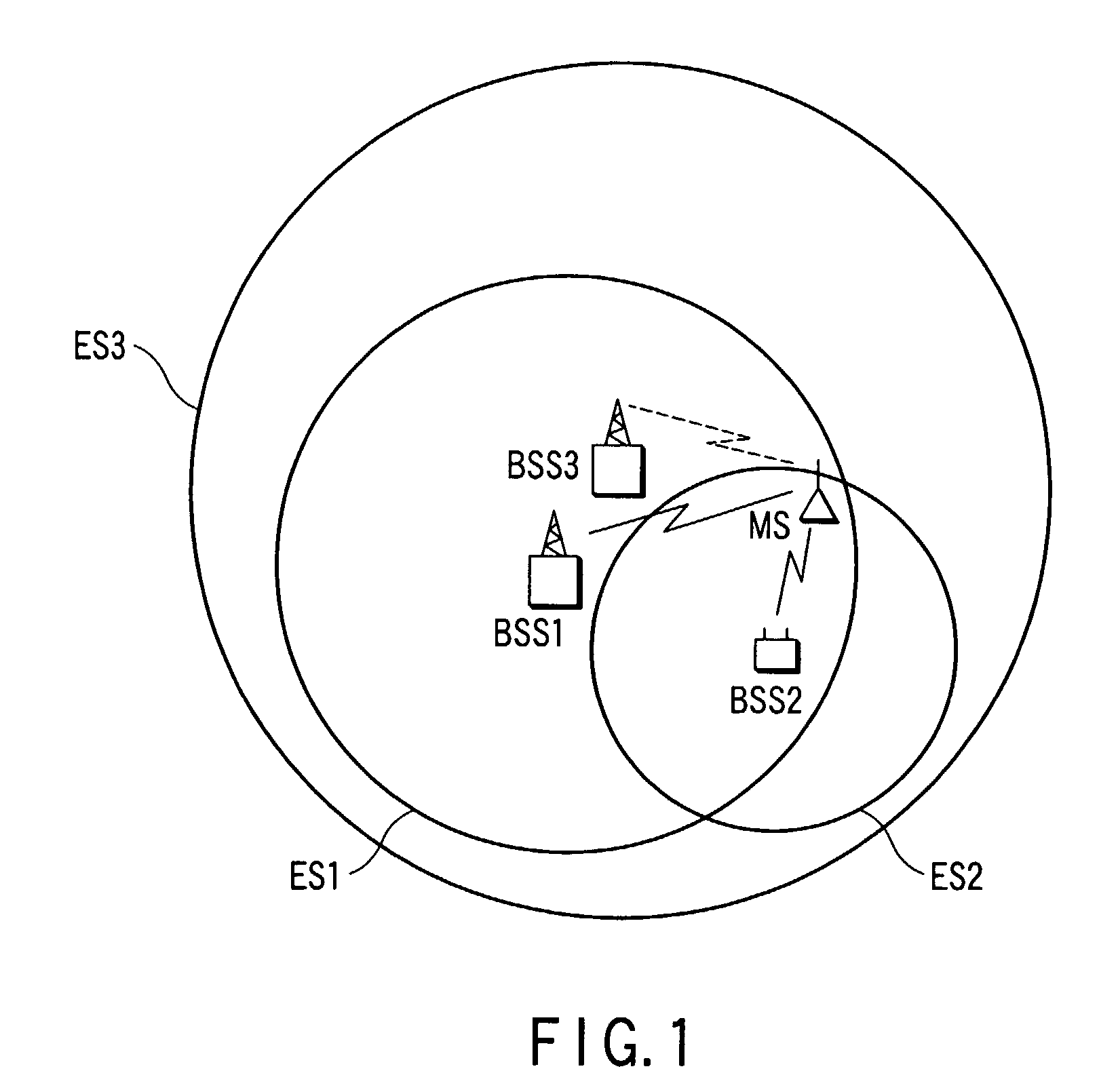
[0018]FIG. 1 is a schematic view showing the state of a service area in which a mobile communication terminal apparatus according to a first embodiment of the present invention is used. In this service area, a plurality of systems (three systems are shown in FIG. 3) operated independently of each other form radio areas ES1, ES2, and ES3. Base stations BSS1, BSS2, and BSS3 are installed in radio areas ES1, ES2, and ES3, respectively, and are connected to mobile communication switching apparatuses (not shown) operated by the individual systems.

[0019]Examples of the plurality of systems are a digital portable communication system using CDMA (Code Division Multiple Access) scheme, a personal mobile communication system called PCS (Personal Communication System) using the same CDMA scheme, and an analog cell phone system using an analog communication system represented by AMPS (Advanced Mobile Phone System).

[0020]For the sake of convenience of explanation, each system h...

second embodiment

(Second Embodiment)

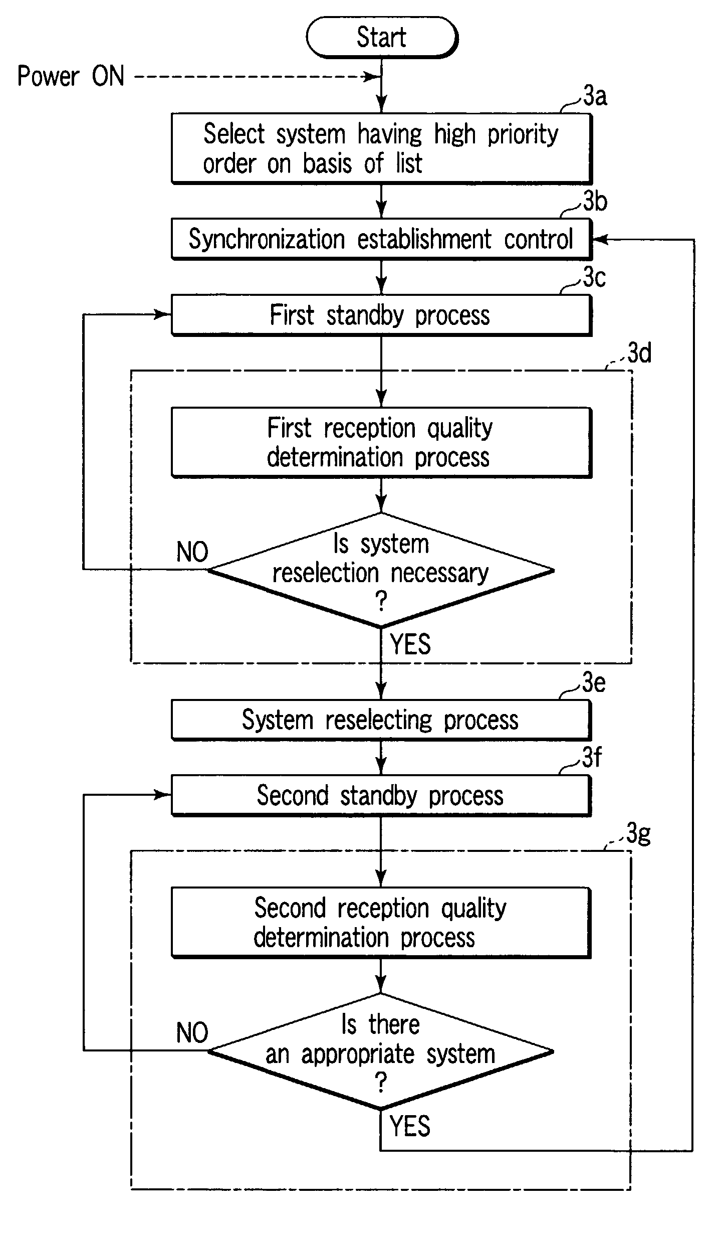
[0063]As shown in FIG. 6, while first system reselection control and second system reselection control are performed in a first standby state (step 3c) and a second standby state (step 3f), respectively, an event which can be a trigger of a system reselecting process is monitored in step 6a. Examples of an event which can be a trigger are “system lost” in the standby state and the termination of communication. The any of these events is detected, a system reselecting process is executed. “System lost” in the standby state is the inability to receive any effective messages in succession for 3 seconds or more in a paging channel receiving period except for a sleep period of an intermittent receiving operation.

third embodiment

(Third Embodiment)

[0064]In the first embodiment, if a system in which both the RSSI and Ec / Io exceed the threshold values Br and Be is detected even once during the second system reselection control, the destination of synchronization establishment is again immediately changed to this detected system. However, as in the first system reselection control, when a system in which both the RSSI and Ec / Io exceed the threshold values Br and Be a plurality of times in succession is found, the destination of synchronization establishment can again be changed to the detected system.

[0065]FIG. 7 is a flowchart showing the procedure and contents of second system reselection control performed by a mobile communication terminal apparatus according to this third embodiment. The same reference symbols as in FIG. 5 denote the same steps in FIG. 7, and a detailed description thereof will be omitted.

[0066]Assume that a system in which both the RSSI and Ec / Io exceed the threshold values Br and Be in st...


PUM


Abstract

In a first standby state, the reception quality of a signal from a system which has established synchronization is detected. If the detected reception quality deteriorates to be less than a threshold value, the destination of synchronization establishment is changed from a first system to a second system. In a second standby state after this system change, the reception quality of a system having a higher priority order of selection than the second system which has established synchronization is detected. If a third system whose detected reception quality exceeds the threshold value is found, the destination of synchronization establishment is changed to this third system again. After that, the first standby state is returned.

Description

CROSS-REFERENCE TO RELATED APPLICATIONS[0001]This application is based upon and claims the benefit of priority from the prior Japanese Patent Application No. 2001-310313, filed Oct. 5, 2001, the entire contents of which are incorporated herein by reference.BACKGROUND OF THE INVENTION[0002]1. Field of the Invention[0003]The present invention relates to a mobile terminal apparatus used in an area in which services are provided by a plurality of cellular mobile communication systems different in communication standards, e.g., a digital cell phone system, analog cell phone system, and PCS (Personal Communication System), and to a system selecting method used to select an optimum system while this mobile terminal apparatus is in a standby state.[0004]2. Description of the Related Art[0005]Generally, when a mobile terminal apparatus used in a cellular mobile communication system is powered on, the apparatus searches for a control signal transmitted by a base station of a system desired by...

Claims


Application Information

Patent Timeline
Patent Type & Authority Patents(United States)
IPC IPC(8): H04B1/38H04W36/14H04W36/36
CPCH04W60/04
Inventor KIYOMOTO, MORIAKIISHIKURA, AKIRASAKAGAWA, TAKASHI
Owner FUJITSU TOSHIBA MOBILE COMM LTD
Why Eureka
Try Eureka