Projection Type Image Display Apparatus

a technology of projection type and image display, which is applied in the direction of printers, cameras, instruments, etc., can solve the problems of loss of light balance, and achieve the effect of reducing color shading and reducing deterioration of white balan

Inactive Publication Date: 2009-06-04
MAXELL HLDG LTD
View PDF2 Cites 8 Cited by
  • Summary
  • Abstract
  • Description
  • Claims
  • Application Information

AI Technical Summary

Benefits of technology

[0015]As described above, according to the invention, it is possible to provide a projection type image display apparatus that eliminates deterioration in white balance and decreases color shading even when deviation in distribution of illumination is generated on a side of a light source.

Problems solved by technology

Therefore, there is caused a problem that balance in light is lost and white balance resulted from superposition of R-light, G-light, and B-light is deteriorated.

Method used


Image

  • Projection Type Image Display Apparatus
  • Projection Type Image Display Apparatus
  • Projection Type Image Display Apparatus

Examples


Embodiment Construction

[0033]The invention will be described hereinafter with reference to the drawings. In addition, the invention is not limited to an example shown in the drawings, the same parts in the respective drawings are denoted by the same reference numerals, and an explanation for parts having been once illustrated is omitted.

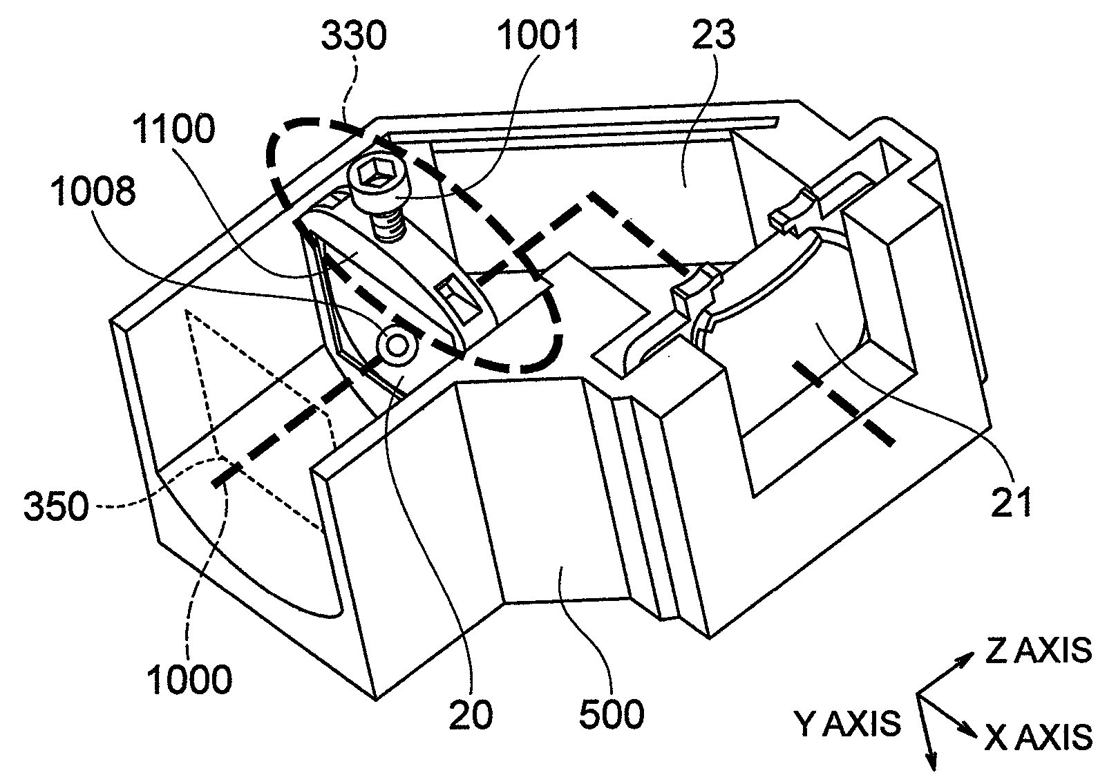
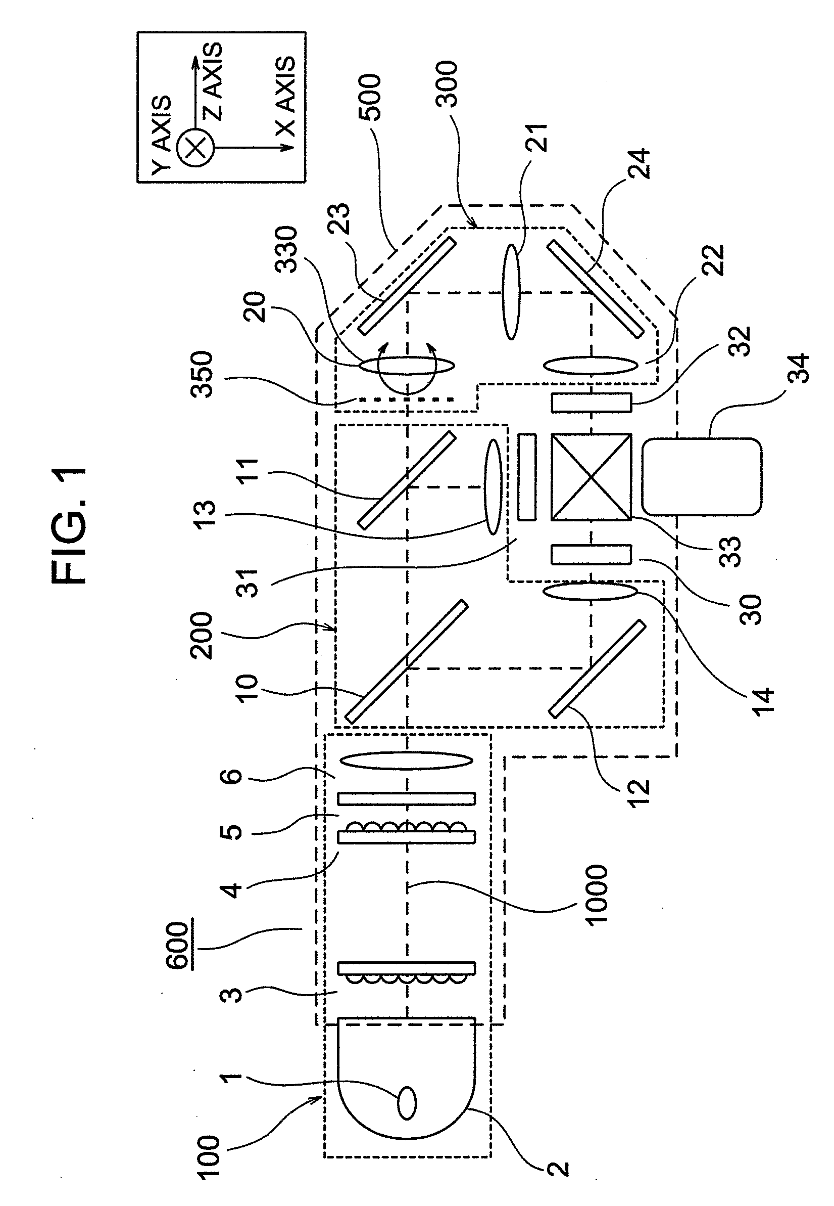
[0034]FIG. 1 is a view schematically showing the construction of an optical system of a projection type image display apparatus according to the invention. Here, a liquid crystal panel is used as an image display element.

[0035]As shown in FIG. 1, the optical system of the projection type image display apparatus comprises an illumination optical system 100 mounted to a base body 500, a color separation optical system 200, a relay optical system 300, two condenser lenses 13, 14, three liquid crystal panels 30, 31, 32, a light combination prism 33, and a projection lens 34.

[0036]These optical elements are mounted on the base body 500 to constitute an optical unit 600, the opt...


PUM


Abstract

A projection type image display apparatus comprising a light source, an optical integrator, by which light outgoing from the light source is changed in distribution of illumination, a color separation optical system, by which light outgoing from the optical integrator is separated into a plurality of light beams, and a relay optical system including a plurality of relay lenses, by which light beams separated by the color separation optical system are relayed, and a reflection mirror. The relay optical system includes a device that adjusts angles of inclination of at least one of the relay lenses with respect to an optical axis of illumination of light outgoing from the light source.

Description

INCORPORATION BY REFERENCE[0001]The present application claims priority from Japanese application JP2007-308155 filed on Nov. 29, 2007, the content of which is hereby incorporated by reference into this application.BACKGROUND OF THE INVENTION[0002]The present invention relates to a technology that provides a projection type image display apparatus.[0003]In a three-plate projection type image display apparatus, optical paths, along which respective colored beams of light having been subjected to color separation reach corresponding liquid crystal panels, are different in optical distance (referred appropriately below to as “optical path length”) and thus at least light of one color is long in optical path length as compared with light of the remaining colors. Hereupon, a relay optical system is used in an optical path of light of a color, which is long in optical path length, to correct an optical path length thereof, which is disclosed in, for example, JP-A-2004-226814.[0004]By the ...

Claims


Application Information

Patent Timeline
Patent Type & Authority Applications(United States)
IPC IPC(8): G03B21/28
CPCG03B21/28
Inventor WATABE, YASUHISAKIMURA, NOBUYUKITAKEUCHI, YOSHIMASAINUI, SHINRO
Owner MAXELL HLDG LTD
Why Eureka
Try Eureka