
Color conversion device and color conversion method

Active Publication Date: 2007-02-13
MITSUBISHI ELECTRIC CORP
View PDF16 Cites 17 Cited by
  • Summary
  • Abstract
  • Description
  • Claims
  • Application Information

AI Technical Summary

Benefits of technology

[0041]The invention has been made to solve the problems described above, and its object is to provide a color conversion device or color conversion method for pixel-by-pixel conversion of image data consisting of a plurality of color data, which can restrain emphasis of effects of noise components in the dark parts of the image, and restrain occurrence of color contraction in the parts of high chroma, or in the light parts, and with which the conversion characteristics can be changed flexibly, and which does not require a memory of a large capacity.
[0043]Accordingly, it is possible to realize color conversion according to the characteristics information of the image data, and even when a processing to increase the chroma of the color data is performed, it is possible to obtain a good color reproduction without further emphasizing the effects of the noise components in dark parts of the image or the like, and even when a processing to increase the chroma of the color data is performed, it is possible to achieve color conversion, avoiding color contraction in the parts of a high lightness or high chroma of the image.
[0044]When only the lightness information of the image data is used as the characteristics information, it is possible to obtain the effects of restraining the emphasis of the noise components in the dark parts of the image, and of restraining the color contraction in the parts of a high lightness of the image, due to the processing to increase the lightness of the color data.
[0045]When only the chroma information of the image data is used as the characteristics information, it is possible to obtain the effects of restraining the color contraction in the parts of a high chroma of the image, due to the processing to increase the chroma of the color data.
[0046]In the color conversion device of the invention, the characteristics information is calculated using both of the lightness information and the chroma information of the image data, so that the effects obtained when only the lightness information is used and the effects obtained when only the chroma information is used, are both obtained, so that a very good color conversion can be achieved.

Problems solved by technology

A problem associated with the table conversion method is the size of the memory required.
Thus, this method requires a memory of a large capacity for each conversion characteristics, and it is difficult to implement the method by means of LSIs.
Another problem is that the method cannot be flexibly adapted to changes in the use conditions or the like.
Also, the color data input to an image display device are not necessarily identical with the original color data generated at a color data source, such as a camera.
Moreover, it is also conceived that some errors may occur in the procedures at the time of transmission and reception.
As a result, in dark parts of the image where the original color components Rs, Gs, Bs are small, the color conversion increases the effects of the noise or the effects of errors during transmission and reception.
However, the conventional color conversion method using the above equation (1), in which color conversion is effected without taking into consideration the characteristics, such as lightness of the color data Ri, Gi, Bi input to the image display device, is associated with the problem that the color conversion increases the effects of the noises or the effects of errors during transmission and reception, in the dark parts of the image where the original color data components Rs, Gs, Bs are small.
As a result, in the dark parts of the image, the effects of the noise components are further increased, and the images displayed on the image display device will become very unpleasant.
Conventional color conversion methods in which the characteristics of the color data Ri, Gi, Bi input to the image display device are not taken into consideration is also associated with a problem that color contraction in which fine differences in colors are lost in light colors by the color conversion may occur.
Moreover, when color conversion to increase the chroma of the colors is conducted in the conventional conversion method in which the characteristics of the color data input to the image display device are not taken into consideration, color contraction by which fine differences in colors are lost at colors of a high chroma may occur.
When the conventional color conversion device or color conversion method is implemented by the table conversion method using a memory such as a ROM, a memory of a large capacity is required, and the conversion characteristics cannot be flexibly changed.

Method used


Image

  • Color conversion device and color conversion method
  • Color conversion device and color conversion method
  • Color conversion device and color conversion method

Examples


embodiment 1

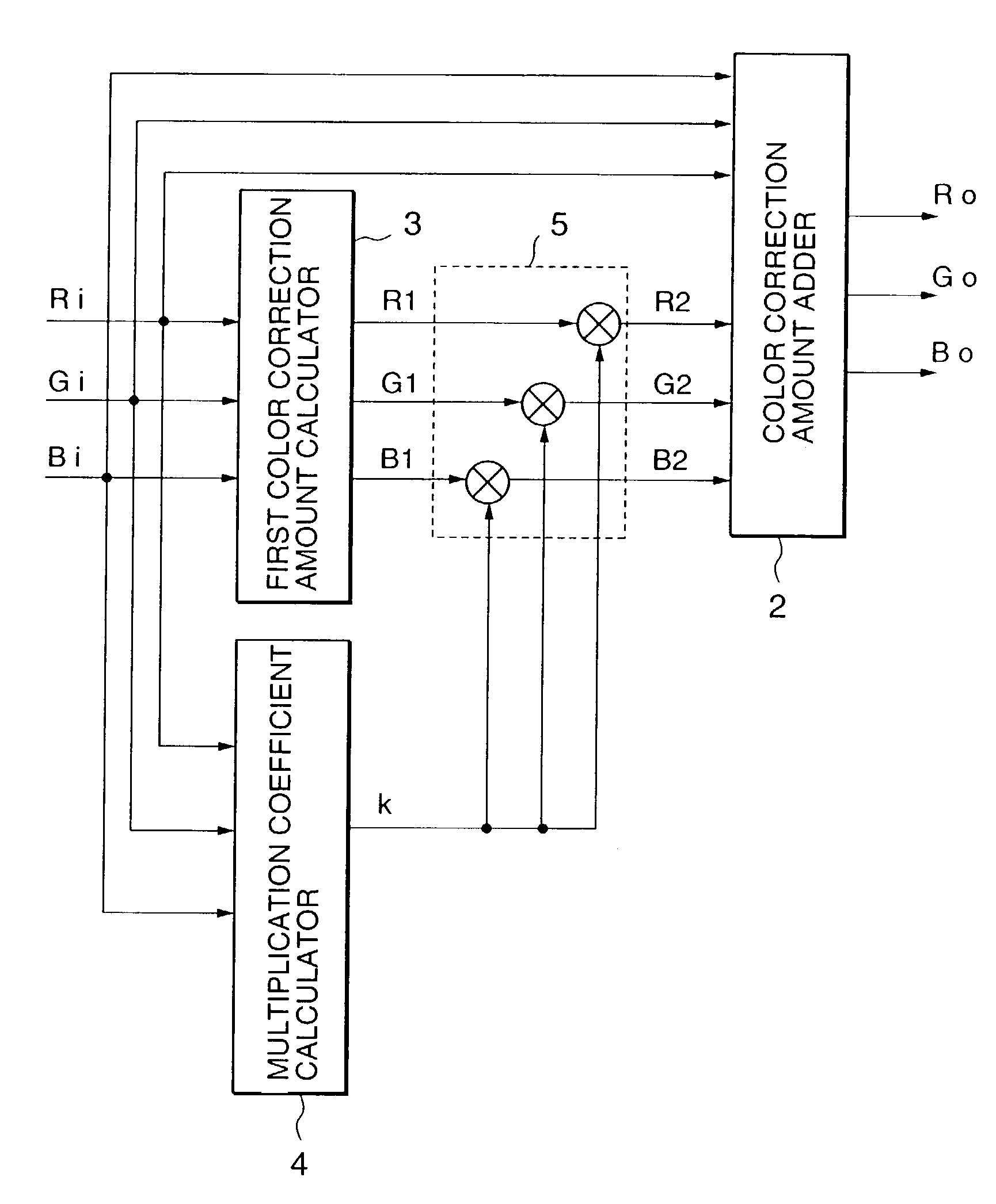
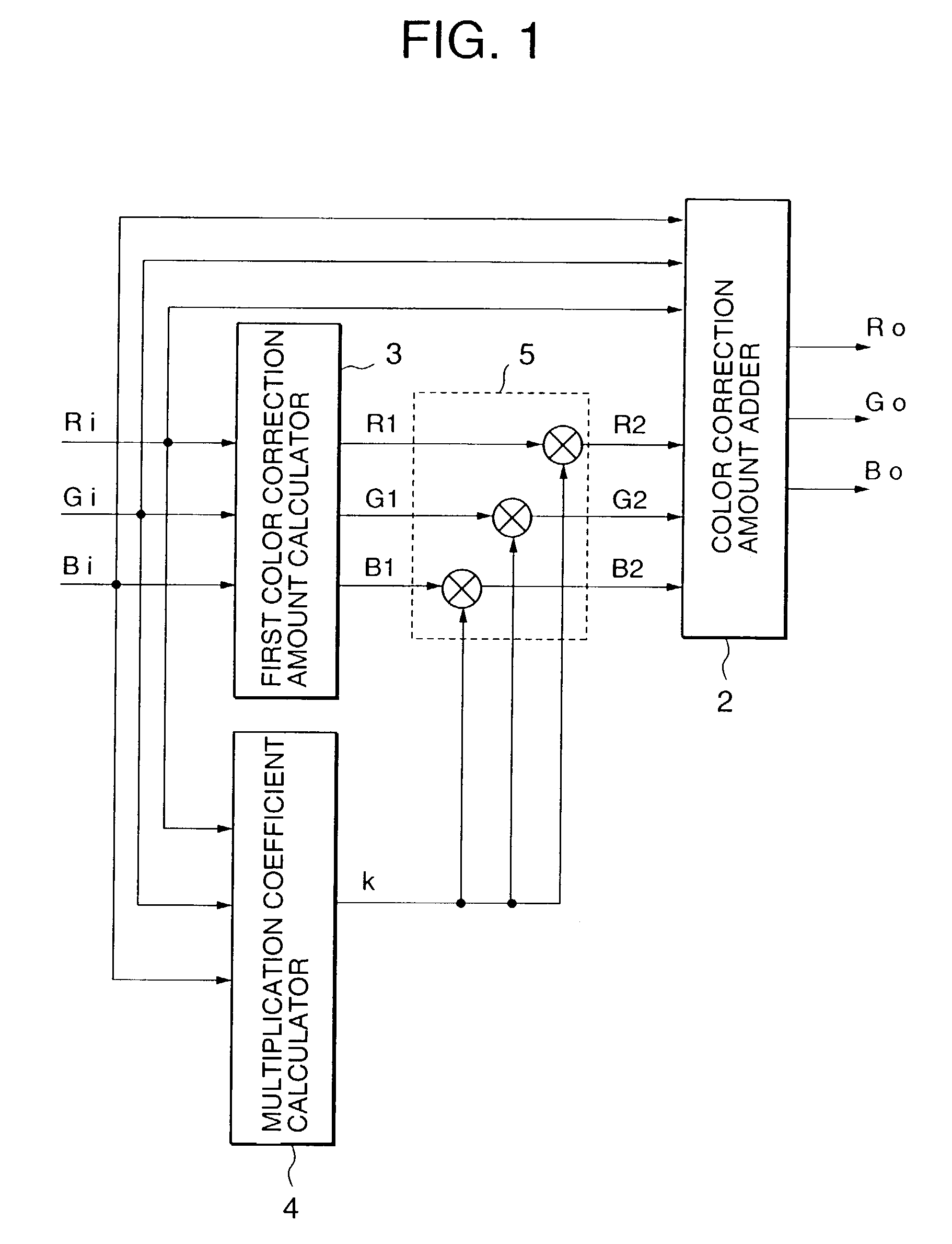
[0071]FIG. 1 is a block diagram showing an example of configuration of a color conversion device according to an embodiment of the invention. The illustrated color conversion device is for performing color conversion on first image data consisting of a plurality of first color data Ri, Gi, Bi and constituting image information for each pixel, to produce second image data consisting of a plurality of second color data Ro, Go, Bo, and constituting image information for each pixel, and comprises a first color correction amount calculator 3, a multiplication coefficient calculator 4, a second color correction amount calculator 5, and a color correction amount adder 2.

[0072]The first color data Ri, Gi, Bi are input to the first color correction amount calculator 3. The first color correction amount calculator 3 calculates first color correction amounts R1, G1, B1 for the first color data Ri, Gi, Bi, and outputs the first color correction amounts R1, G1, B1 to the second color correction ...

embodiment 2

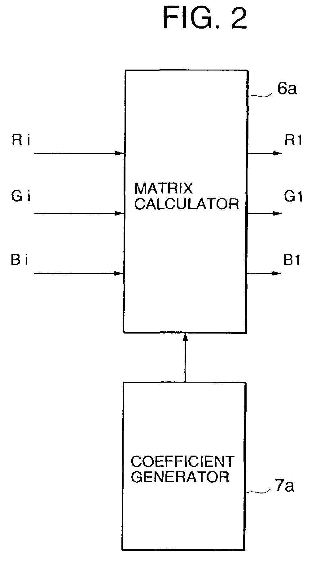
[0123]FIG. 10 is a block diagram showing another example of configuration of first color correction amount calculator 3 in a color conversion device according to Embodiment 1 of the present invention. In the drawing, reference numeral 18 denotes an αβ calculator calculating and outputting a maximum value β and a minimum value α of the input first color data first color data Ri, Gi, Bi, and generating and outputting an identification code indicating which of the first color data is the maximum and which of the first color data is the minimum. Reference numeral 19 denotes a hue data calculator calculating hue data r, g, b, y, m, c from the first color data Ri, Gi, Bi and the outputs of the αβ calculator 1. Reference numeral 20 denotes a polynomial calculator, 6b denotes a matrix calculator, and 7b denotes a coefficient generator.

[0124]FIG. 11 is a block diagram showing an example of configuration of the polynomial calculator 20. In the drawing, reference numeral 21 denotes a zero remo...


PUM


Abstract

In a color conversion device, first color correction amounts are determined from first image data consisting of a plurality of first color data, and second color correction amounts are determined from characteristics information of the first image data is calculated, and the first color correction amounts. The second color correction amounts are added to the first image data, to determine the second image data. The characteristics information is determined by calculating the characteristics information by a calculation using the lightness information and the chroma information of the first image data, so that color conversion reflecting characteristics information including the lightness information and the chroma information of the image is achieved.

Description

BACKGROUND OF THE INVENTION[0001]1. Field of the Invention[0002]The present invention relates to data processing used for example in full-color printing related equipment, such as printers, video printers, scanners, or the like, or image processing equipment such as those for generating computer-graphics images, or display devices such as monitors, and in particular to an image processing device and method for image-processing the image data represented by three colors of red, green and blue, to be suitable for the equipment used.[0003]2. Description of Related Art[0004]Color conversion in printing is an essential image technology for compensating for deterioration of printed images, due to color-mixing property caused by the fact that inks are not of pure colors, and due to non-linearity of the image printing, and outputting printed images with a good color reproducibility. In display devices, such as monitors, color conversion is effected for outputting (displaying) an image with ...

Claims


Application Information

Patent Timeline
IPC IPC(8): G06K9/00G06T1/00H04N1/46H04N1/60
CPCH04N1/60H04N9/64
Inventor KAGAWA, SHUICHISUGIURA, HIROAKI
Owner MITSUBISHI ELECTRIC CORP
Learn More