Clips for holding fiber optic cables of a security fence
What is AI technical title?
AI technical title is built by Patsnap AI team. It summarizes the technical point description of the patent document.
a technology for security fences and fiber optic cables, applied in the field of clips, can solve problems such as the exposure of the flattened end, and achieve the effects of easy manufacture, easy installation, and easy breakage or cutting
Inactive Publication Date: 2007-02-13
HUNEED TECH
View PDF44 Cites 36 Cited by
Summary
Abstract
Description
Claims
Application Information
AI Technical Summary
This helps you quickly interpret patents by identifying the three key elements:
Problems solved by technology
Method used
Benefits of technology
Benefits of technology
"The present invention provides a clip for holding fiber optic security fencing in a given pattern. The clip is stronger and more difficult to break or cut than previous clips, making it more secure against intruders. The clip is easy to manufacture, inexpensive, and easy to install. The technical effects of the invention are that it prevents intruders from disconnecting the pattern of the fiber optic cable, in order to cut through the barrier fence and gain entry into a secure area."
Problems solved by technology
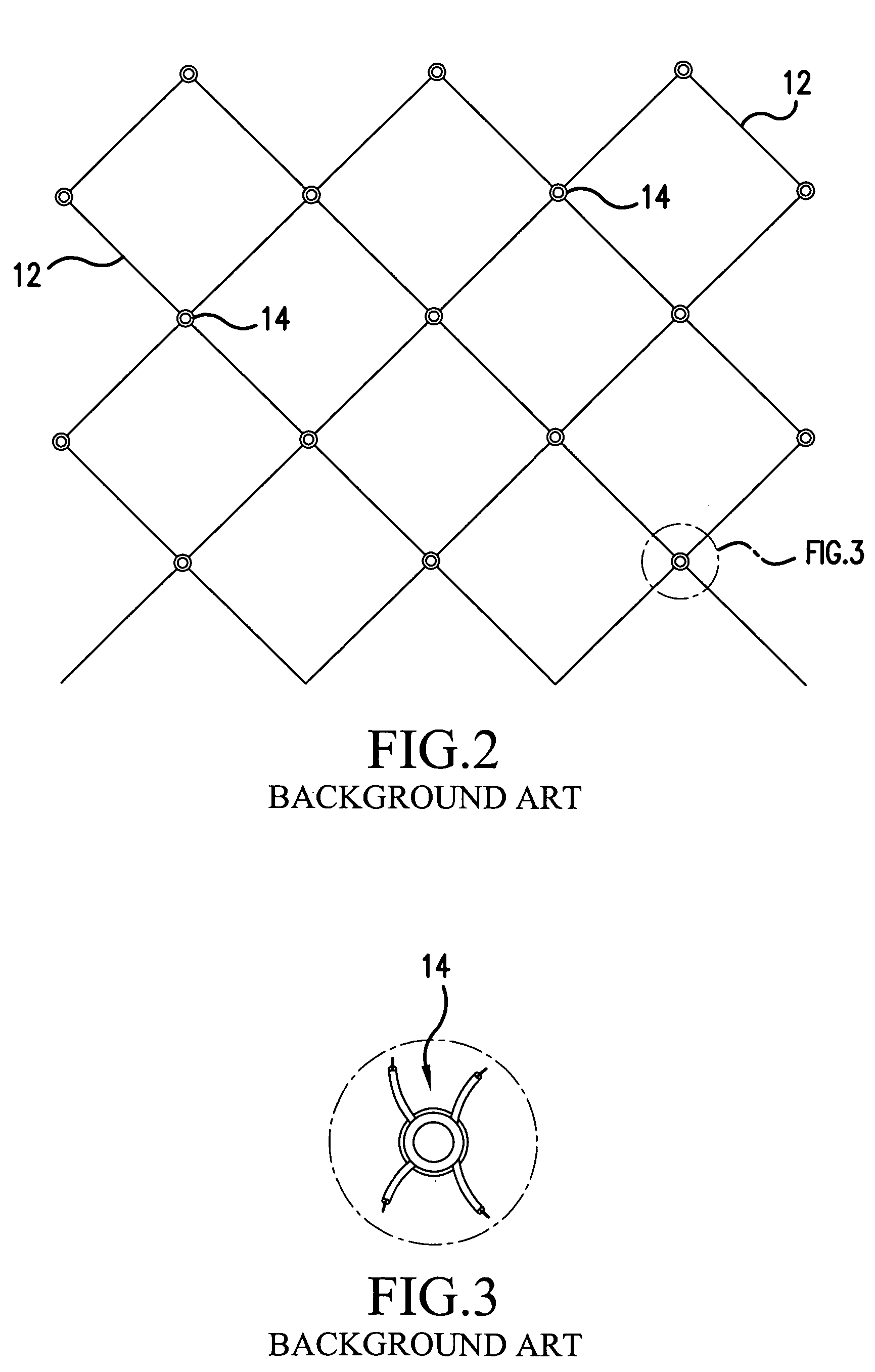
The Applicant has discovered drawbacks in the state of the art clips for holding a fiber optic security fence into a given pattern.
Another potential drawback is the exposure of the flattened end 23 of the stem portion 20.
Method used
Image
Click on the blue label to locate the original text in one second.
Reading with bidirectional positioning of images and text.
Examples
Embodiment Construction
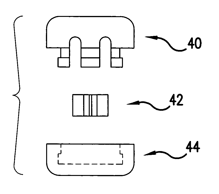
[0038]Referring to FIG. 7, a clip, in accordance with the present invention, generally includes a first part 40, an insert 42 and a second part 44. With reference to FIGS. 7–12, the first part 40 has the appearance of a circular disc when viewed from its top (FIG. 9).
[0039]A bottom of the first part 40 (FIGS. 8 and 10) is more complex in shape. A first curved channel 46 and a second curved channel 48 form geometric cords to the outer perimeter of the first part 40. The first and second curved channels 46 and 48 meet in a central space 50 formed in the bottom of the first part 40. Hence, the first and second curved channels 46 and 48 form an embedded X-shape in the bottom of the first part 40.
[0040]The first part 40 includes a first stepped ledge 52. The first stepped ledge 52 extends radially inward from an outermost periphery of the bottom of the first part 40.
[0041]Engagement walls 54 extend down from the first stepped ledge 52. As illustrated in FIGS. 7, 8, 11 and 12, the engagem...
PUM
Abstract
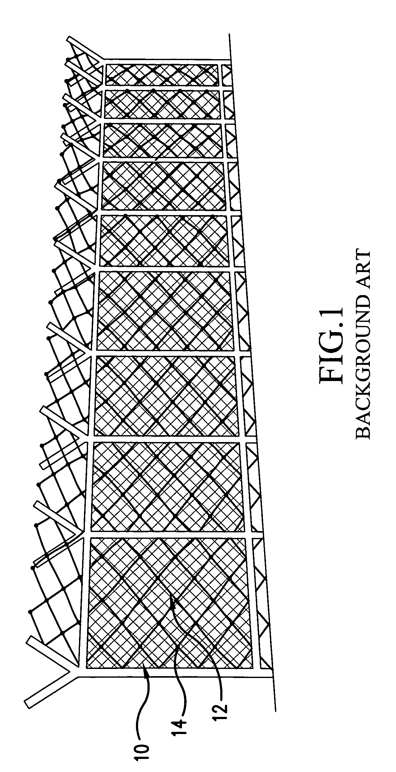
A clip for holding a first section of fiber optic cable to a second section of fiber optic cable is useful in forming a weave pattern in a fiber optic security fence. The fiber optic security fence is constructed by forming a zigzag pattern in a fiber optic cable and attaching this pattern to an existing barrier fence, e.g. a galvanized chain-link fence. Clips are provided to hold portions of the fiber optic cable together in the zigzag pattern. The clips are formed such that, once installed, they are very difficult to remove without cutting, stressing or bending the fiber optic cable sections passing therethrough. Therefore, the clips will prevent intruders from disconnecting the pattern of the fiber optic cable, in order to cut through the barrier fence and gain entry into a secure area.
Description
BACKGROUND OF THE INVENTION[0001]1. Field of the Invention[0002]The present invention relates to a security fence employing a fiber optic cable formed in a pattern and to attached to the security fence to monitor the integrity of the fence against intrusion or tampering. More particularly, the present invention relates to a clip for holding portions of the fiber optic cable, so as to securely hold the fiber optic cable into the pattern.[0003]2. Description of the Related Art[0004]Security fences employing a fiber optic cable monitoring scheme are generally known in the background. For example, see applicant's prior application Ser. No. 10 / 713,425 filed Nov. 17, 2003, entitled “APPARATUS AND METHOD TO DETECT AN INTRUSION POINT ALONG A SECURITY FENCE,” which is herein fully incorporated by reference. Also see U.S. Pat. Nos. 4,275,294; 4,371,869; 4,399,430; 4,450,434; 4,558,308; 4,676,485; 4,680,573; 5,134,386; 5,416,467; 5,592,149; and the assignees prior Korean Patents 1997-0009968, ...
Claims
Application Information
Patent Timeline
Application Date:The date an application was filed.
Publication Date:The date a patent or application was officially published.
First Publication Date:The earliest publication date of a patent with the same application number.
Issue Date:Publication date of the patent grant document.
PCT Entry Date:The Entry date of PCT National Phase.
Estimated Expiry Date:The statutory expiry date of a patent right according to the Patent Law, and it is the longest term of protection that the patent right can achieve without the termination of the patent right due to other reasons(Term extension factor has been taken into account ).
Invalid Date:Actual expiry date is based on effective date or publication date of legal transaction data of invalid patent.

