Stacked-plate gas-expansion cooler assembly, fabrication method, and use

a gas expansion cooler and stacked plate technology, applied in the direction of lighting and heating apparatus, container discharging methods, instruments, etc., can solve the problems of unacceptably long, cryogenic operating temperature on the order, time required to cool the light sensor from room temperature, etc., to achieve the effect of absorbing greater heat from the cooled device and increasing cooling power

Inactive Publication Date: 2007-02-20
RAYTHEON CO
View PDF21 Cites 5 Cited by
  • Summary
  • Abstract
  • Description
  • Claims
  • Application Information

AI Technical Summary

Benefits of technology

[0009]The present approach provides a gas-expansion cooler assembly which rapidly removes heat from the structure to be cooled, such as a microelectronic device. The cooling may be to a cryogenic temperature. The cooler may be integral with the microelectronic system rather than being separate from it as in conventional cold-finger pedestal designs. There is a shorter path from the microelectronic system to the cold sink and fewer interfaces between the microelectronic system and the cold sink than in conventional coolers (and in some cases no interfaces), with less thermal impedance as a result. The microelectronic system or other device is therefore cooled from a higher temperature to its service temperature, which may be a cryogenic service temperature, more rapidly than in conventional designs. The size and weight of the microelectronic system are reduced as compared with conventional Joule-Thomson coolers. In the case where the microelectronic system is a light-sensor system, the performance of the sensor system is improved because the light sensor is not cantilevered at the end of an arm, so that there is less susceptibility to vibration.
[0015]There may optionally be provided an anti-plugging structure that prevents plugging of the expansion orifice by solid matter.
[0020]A virtue of the present approach is that additional cooling power may be added by adding more heat-exchanger plates to the stack. The additional plates allow more gas to be pre-cooled, leading to an ability to absorb greater heat from the cooled device.

Problems solved by technology

One of their drawbacks, however, is that the time required to cool the light sensor from room temperature to its cryogenic operating temperature may be on the order of one minute.
For some applications, that cooldown time may be acceptable, but for other applications, such as military applications, it may be unacceptably long.
Additionally, the light sensor is cantilever mounted on the end of the cold-finger pedestal, increasing the susceptibility of the signals to degradation due to vibration.

Method used


Image

  • Stacked-plate gas-expansion cooler assembly, fabrication method, and use
  • Stacked-plate gas-expansion cooler assembly, fabrication method, and use
  • Stacked-plate gas-expansion cooler assembly, fabrication method, and use

Examples


Embodiment Construction

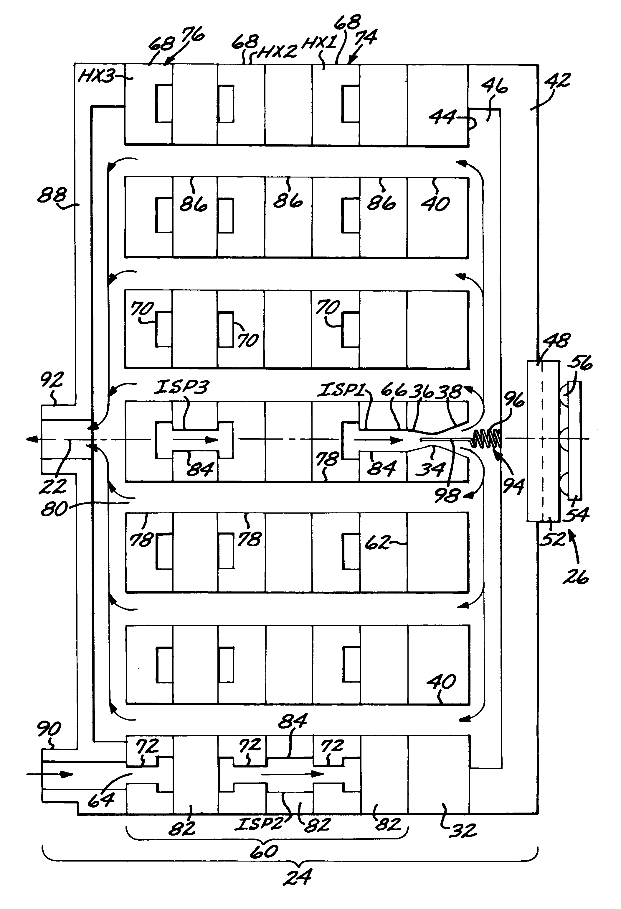
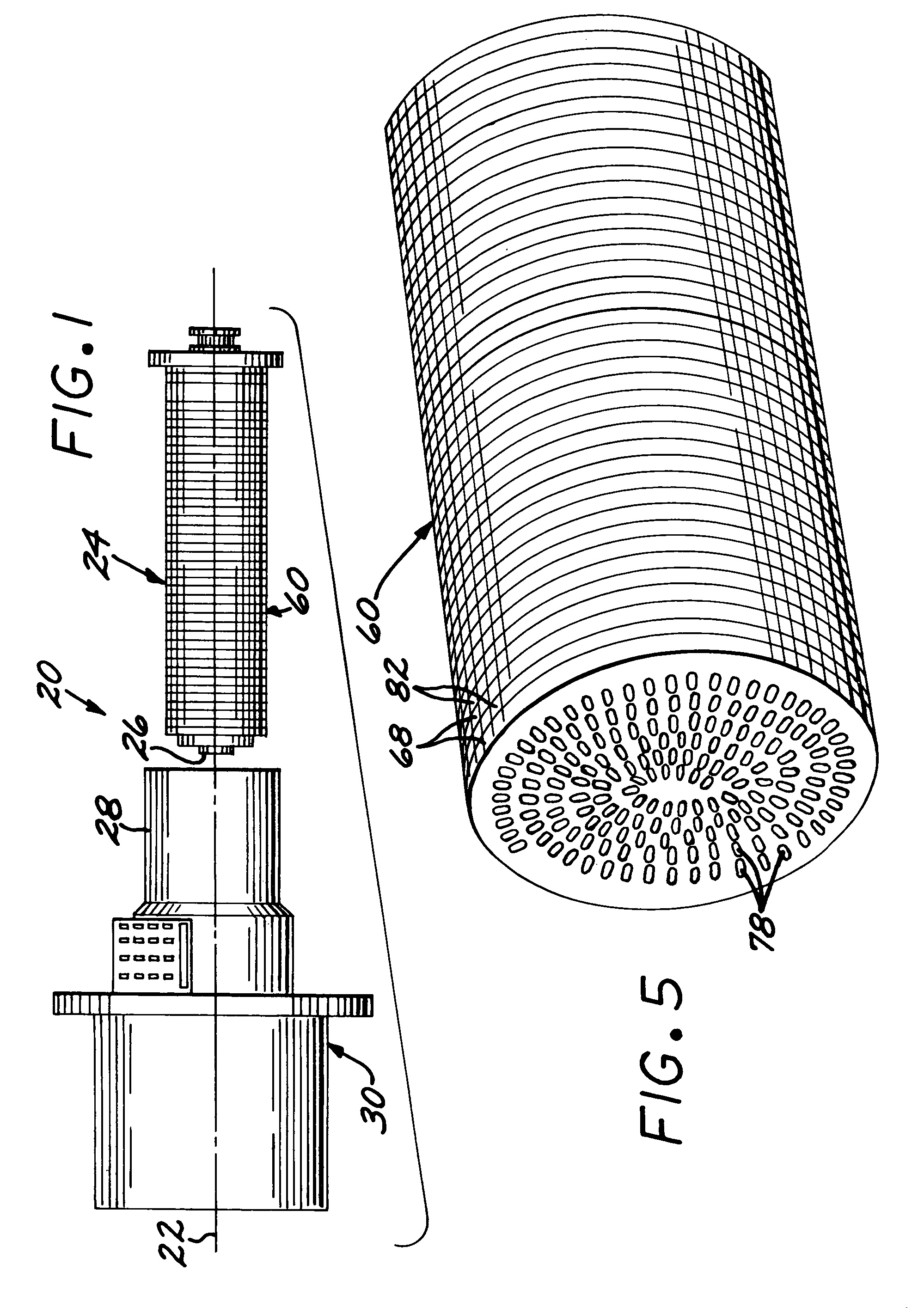
[0027]FIG. 1 depicts in partially exploded view a gas-expansion cooler assembly 20 having an assembly axis 22. The gas-expansion cooler assembly 20 includes a gas expansion cooler 24, and a cooled device 26 mounted thereto. The gas-expansion cooler 24 and cooled device 26 are received in a fitting 28 of a vacuum dewar 30.

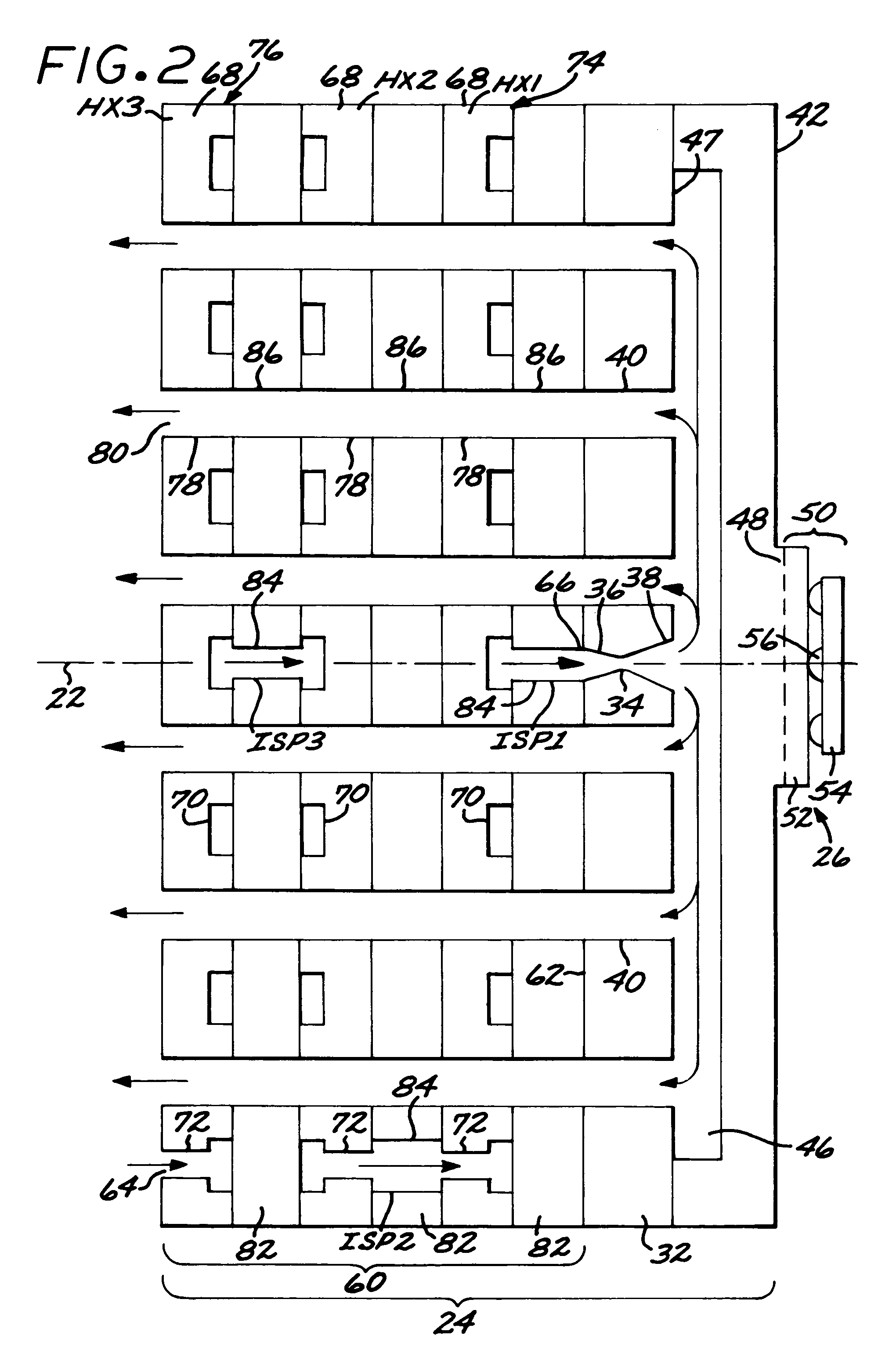
[0028]As seen in FIGS. 2 and 3, a preferred form of the gas-expansion cooler 24 is made of a series of plates having gas-flow channels therein. The embodiments of FIGS. 2 and 3 are similar, and the same description is applicable to both figures except as will be discussed subsequently. The plates that form the gas-expansion cooler 24 are all substantially flat, so that they may be stacked together. The plates all preferably have a cylindrical periphery, so that they form a cylindrical structure as shown in FIG. 1 and in FIGS. 4–5.

[0029]The gas-expansion cooler 24 includes an expansion plate 32 having an expansion orifice 34 therein. The expansion orifice 34 has an e...


PUM


Abstract

A gas-expansion cooler assembly has an expansion structure with an expansion orifice and an expansion reservoir in fluid-flow communication with an expansion-orifice outlet. A heat exchanger has a heat-exchanger inlet, and a heat-exchanger outlet in fluid-flow communication with the expansion-orifice inlet. The heat exchanger includes at least two heat-exchanger plates stacked in a facing relationship along an assembly axis. Each heat-exchanger plate includes an in-plane channel lying substantially in a plane perpendicular to the assembly axis. The in-plane channels of the adjacent heat-exchanger plates are in fluid-flow communication with each other and with the expansion-orifice inlet to form a continuous high-pressure fluid-flow path from the heat-exchanger inlet to the expansion-orifice inlet. The heat exchanger further includes an axial channel extending parallel to the assembly axis. The axial channels in the adjacent heat-exchanger plates are in fluid-flow communication with each other and with the expansion reservoir to form a continuous exhaust fluid-flow path from the expansion reservoir to an exhaust port.

Description

[0001]This application is a continuation in part of application Ser. No. 09 / 952,513, filed Sep. 7, 2001 now U.S. Pat. No. 6,621,071, for which priority is claimed and whose disclosure is incorporated by reference.[0002]This invention relates a to gas-expansion cooler assembly and, more particularly, to the gas-expansion cooler assembly that rapidly cools an electronic system when placed into service.BACKGROUND OF THE INVENTION[0003]In one type of imaging infrared sensor system, a microelectronic light sensor is deposited on a substrate. The substrate is supported on a cold-finger pedestal. The other end of the pedestal is cooled by a gas-expansion cooler such as a Joule-Thomson cooler. The light sensor achieves its most efficient operation and highest signal-to-noise ratio when cooled to a cryogenic temperature such as liquid nitrogen temperature or lower. The light sensor and the cold-finger pedestal are placed inside a vacuum enclosure which has a window facing the light sensor an...

Claims


Application Information

Patent Timeline
Patent Type & Authority Patents(United States)
IPC IPC(8): F25B19/02F28D7/10F28F3/00F17C13/00F25B9/02H01L23/44
CPCF17C13/006F25B9/02H01L23/445H01L2924/3011H01L2924/0002H01L2924/00
Inventor SOBEL, LARRY D.CAPARA, JEFFJENIA, JUSTIN C.
Owner RAYTHEON CO
Why Eureka
Try Eureka