Engine cylinder-to-cylinder variation control

a technology of engine cylinders and variations, applied in the direction of electric control, combustion engines, machines/engines, etc., can solve the problems of different iemp produced by each cylinder, different iemp time and phase of combustion events between the cylinders, and differences in combustion efficiency

Active Publication Date: 2007-02-20
GM GLOBAL TECH OPERATIONS LLC
View PDF2 Cites 37 Cited by
  • Summary
  • Abstract
  • Description
  • Claims
  • Application Information

AI Technical Summary

Problems solved by technology

This results in variations in ignition delay for the various cylinders which, in turn, cause combustion events to be timed and phased differently between the cylinders.
There are also variations in actual compression ratio between cylinders which cause differences in efficiency of combustion and thus a difference in IEMP produced by each cylinder.
In addition, fuel quality differences from one fill-up to the next also may cause the engine to run differently.
State-of-the-art controls do not have the capability to identify the complex combinations of different sources of variation causing cylinders to produce varying power and emissions.

Method used


Image

  • Engine cylinder-to-cylinder variation control
  • Engine cylinder-to-cylinder variation control
  • Engine cylinder-to-cylinder variation control

Examples


Embodiment Construction

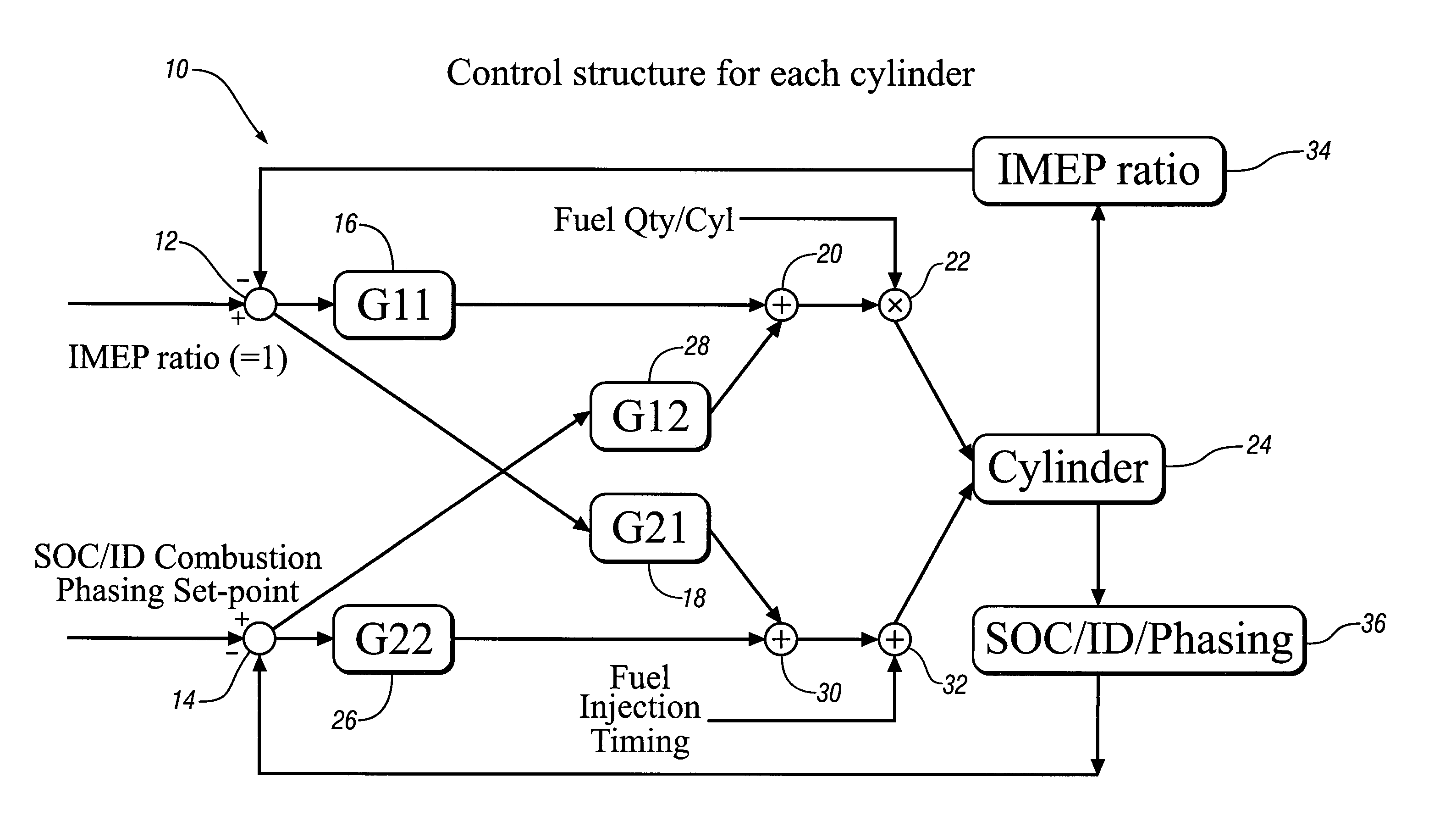
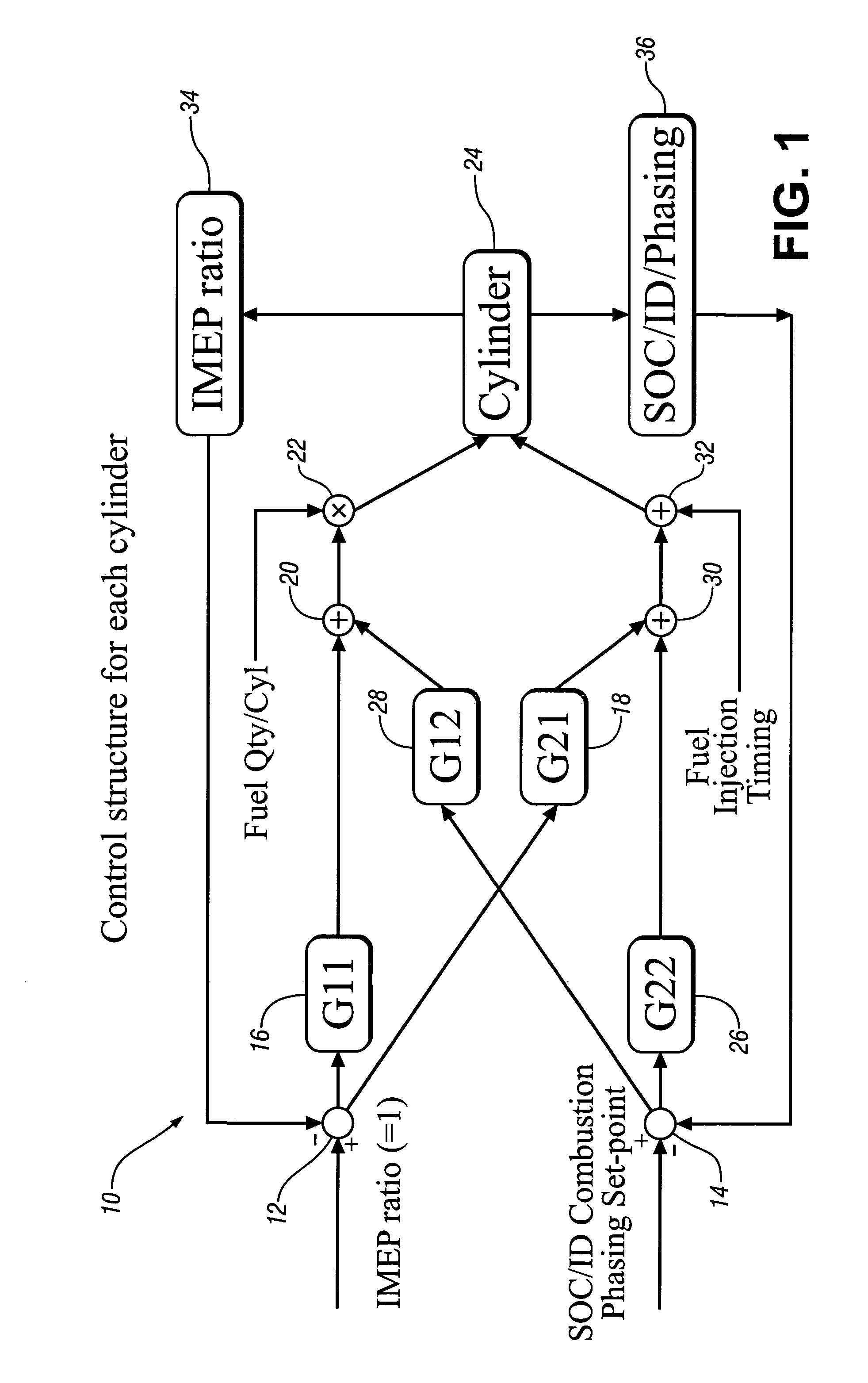
[0012]Referring now to the drawing in detail, numeral 10 generally indicates an exemplary control system for carrying out one embodiment of a control method according to the invention. System 10 includes two separate set-points, a first set-point 12 for IMEP ratio and a second selected phasing set-point 14, such as start of combustion (SOC) (or other phasing variables, auch as ID—ignition delay, LPP—location of peak pressure, heat release shape, or MFBXX—percent mass fraction of burned fuel). Set-point 12 communicates with two proportional integral (PI) controllers, an IMEP controller 16 and a SOC controller 18, assuming SOC is the phasing variable.

[0013]Controller 16 connects at a summation point 20 where signals are added, as will be noted later. Point 20 further connects with a multiplying point 22 where fuel quantity per cylinder is combined with the signals from the summation point 20. The result is used for each engine cylinder 24 to control the fuel injector to inject the pro...


PUM


Abstract

A control system and method for balancing output and exhaust emission values of the various cylinders of an engine having individual cylinder fuel delivery control. Selected output and emission related values for one cylinder, selected as a base cylinder, are compared to the same values for the other cylinders, and fuel injection quantity and timing (or another combustion phasing variable) are adjusted in the other cylinders to output and emission values of the base cylinder. The adjustments are weighted based on the degree to which changes in both the injection quantity and timing (or other variable) influence changes in both the output and emission values as determined from the sensed readings of pressure sensors in each of the cylinders.

Description

TECHNICAL FIELD[0001]This invention relates to balancing of cylinder-to-cylinder variations in engines, such as diesel engines, using cylinder pressure based feedback and multivariable control.BACKGROUND OF THE INVENTION[0002]In a direct injection (DI) diesel engine, there is often a significant spread in the fuel injector hardware from cylinder-to-cylinder. This causes significant variations in how much fuel is actually injected in the various engine cylinders. There are also significant variations in how much recirculated exhaust gas (EGR) is trapped in the various cylinders due to variations in EGR distribution in the intake manifold. This results in variations in ignition delay for the various cylinders which, in turn, cause combustion events to be timed and phased differently between the cylinders. These differences result in producing different work outputs or indicated mean effective pressures (IMEP) from the various cylinders, as well as differing levels of emission products...

Claims


Application Information

Patent Timeline
Patent Type & Authority Patents(United States)
IPC IPC(8): F02M7/00
CPCF02D35/023F02D35/028F02D41/0085F02D41/1401F02D41/40Y02T10/44F02D2041/1409F02D2041/1418F02D2041/1427Y02T10/40
Inventor GANGOPADHYAY, ANUPAM
Owner GM GLOBAL TECH OPERATIONS LLC
Why Eureka
Try Eureka