Vehicular illumination lamp

a technology of vehicular illumination and lamp units, which is applied in the direction of fixed installation, lighting and heating equipment, lighting support devices, etc., can solve the problems of many such lamp units and the limitation of the brightness of the light distribution pattern formed by light emitted, and achieve the effect of good accuracy and the number of such vehicular illumination lamps

Inactive Publication Date: 2007-02-20
KOITO MFG CO LTD
View PDF5 Cites 35 Cited by
  • Summary
  • Abstract
  • Description
  • Claims
  • Application Information

AI Technical Summary

Benefits of technology

[0013]There is no specific limitation on the number and a specific arrangement of the plurality of light emitting devices, For example, circumferential intervals between the respective light emitting devices may be or may not be set to an equal value. However, if the plurality of light emitting devices are disposed around a circumference of an axis which passes through a predetermined center point at substantially equal intervals with respect to the axis, the respective reflecting surfaces can be formed into substantially the same shape of the same size, and the utilization factor of bundles of rays of light from the plurality of light emitting devices can be enhanced.
[0015]Since the light distribution control member can control the light distribution of light from the respective light emitting devices that is reflected on the reflector as diffused light from the predetermined point, a sufficient brightness can be secured for a light distribution pattern that is formed by light emitted from the vehicular illumination lamp. Moreover, as this occurs, the light distribution control can be implemented with good accuracy. By adopting this configuration, the number of such vehicular illumination lamps required when the vehicular illumination lamp of the invention is attempted to be used as a headlamp can be reduced.

Problems solved by technology

In the vehicular illumination lamp described in the aforesaid JP '513, however, since the light source is made up of the single light emitting device, there is a limitation on the brightness of a light distribution pattern that is formed by light emitted from the light source, even if the utilization factor of a bundle of rays of light emitted from the light emitting device is enhanced to a maximum level.
Consequently, in a case where this vehicular illumination lamp is used as a lamp unit for a headlamp, there is a problem that many such lamp units are necessary.

Method used


Image

  • Vehicular illumination lamp
  • Vehicular illumination lamp
  • Vehicular illumination lamp

Examples


Embodiment Construction

[0027]Although the invention will be described below with reference to an exemplary embodiment and modifications thereof, the following exemplary embodiment and modifications do not restrict the invention.

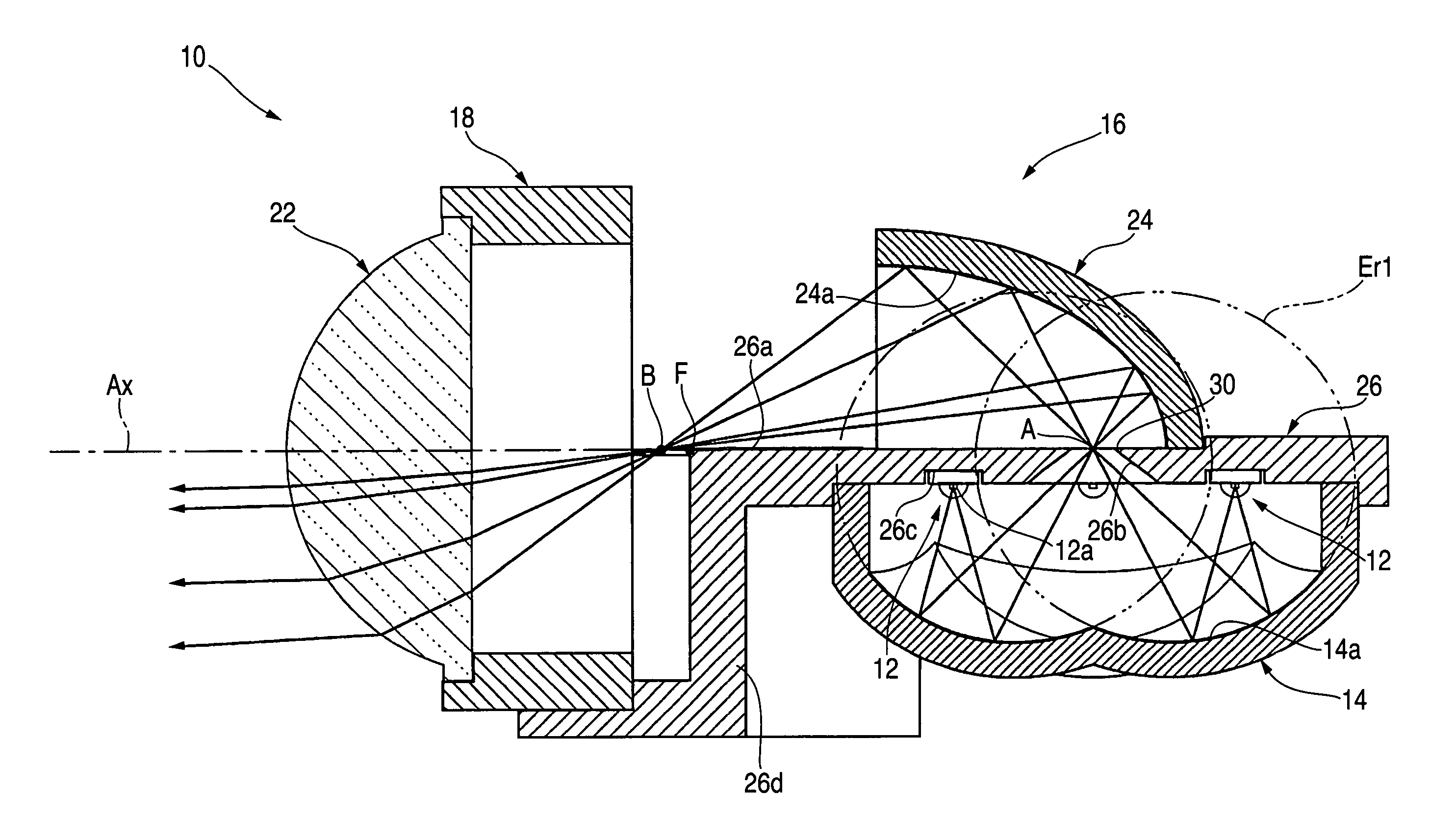
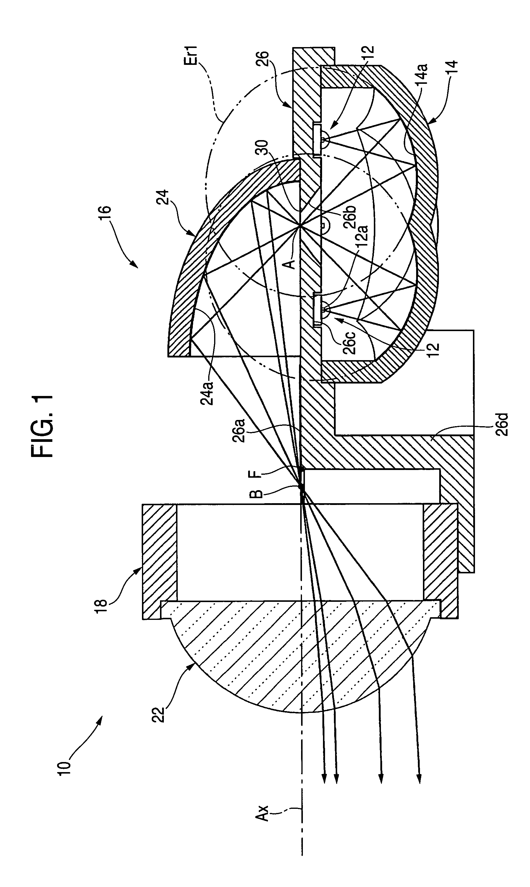
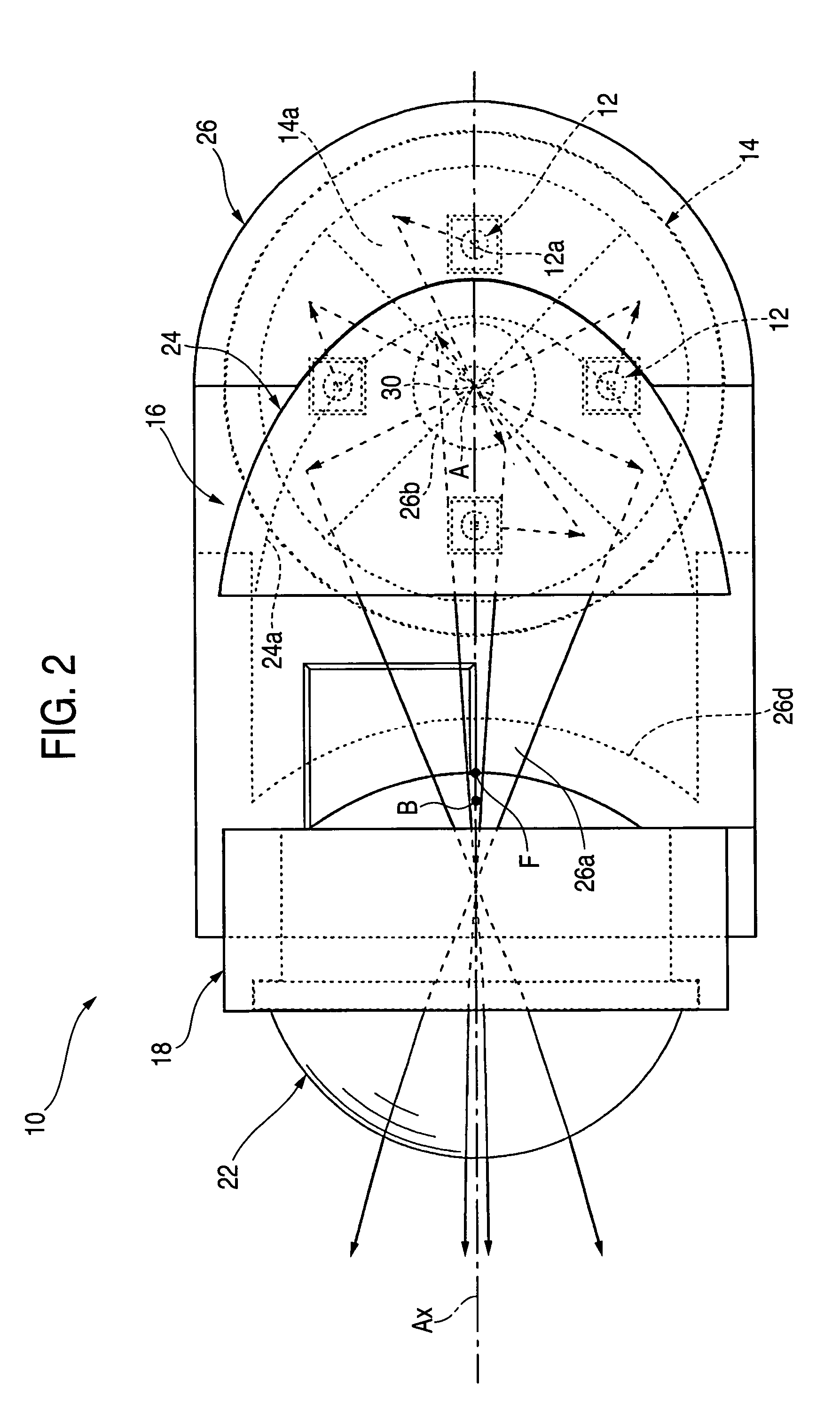
[0028]FIG. 1 is a side sectional view which shows a vehicular illumination lamp 10 according to an exemplary embodiment of the invention. FIGS. 2 and 3 are a plan view and a front view thereof, respectively.

[0029]As shown in these figures, this vehicular illumination lamp 10 includes four light emitting devices 12, a reflector 14, and a light distribution control member 16. The four light emitting devices 12 are disposed around a predetermined center point A and lie on an optical axis Ax, which extends along a longitudinal direction of the lamp. The reflector 14 reflects light upwards from these respective light emitting devices 12. The light distribution control member 16 controls the distribution of light from the respective light emitting devices 12 that is reflected on the refl...


PUM


Abstract

A vehicular illumination lamp, including four light emitting devices 12 which are disposed in such a manner as to spread about a predetermined point A as a center, a reflector 14 having four reflecting surfaces 14a that are made up of ellipsoids of revolution Er1, which take light emitting centers of the respective light emitting devices 12 and the predetermined point A as primary focal points and secondary focal points thereof, respectively, and a light distribution control member 16, which controls the light distribution of light from the respective light emitting devices 12 that is reflected on the reflector 14 so as to cause the light so controlled to traverse to a front of the lamp, whereby light emitted from the respective light emitting devices 12 is made first to be reflected on the respective reflecting surfaces 14a and is then caused to converge on the predetermined point A.

Description

[0001]This application claims foreign priority from Japanese Patent Application No. 2004-357459, filed Dec. 9, 2004, the entire disclosure of which is herein incorporated by reference.BACKGROUND OF THE INVENTION[0002]1. Field of the Invention[0003]The present invention relates to a vehicular illumination lamp that utilizes a light emitting device as a light source.[0004]2. Related Art[0005]In recent years, vehicular illumination lamps, which utilize light emitting devices such as light emitting diodes as light sources, have been proposed for adoption as headlamps or the like.[0006]For example, Japanese Patent Publication No. 2003-317513 (“JP '513”) describes a so-called projector type vehicular illumination lamp, which includes a projection lens disposed on an optical axis which extends in a longitudinal direction of the lamp and a light source unit disposed rearwards of the projection lens. The light source unit of the vehicular illumination lamp described in JP '513 is configured ...

Claims


Application Information

Patent Timeline
Patent Type & Authority Patents(United States)
IPC IPC(8): F21S8/10
CPCF21S48/1159F21S48/1163F21S48/1241F21S48/1388F21S48/1291F21V7/0091F21S48/145F21V7/0008F21Y2101/02F21Y2115/10F21S41/147F21S41/24F21S41/255F21S41/27F21S41/321F21S41/322F21S41/323F21S41/37F21S41/43F21S41/365F21S41/151F21S41/148
Inventor ISHIDA, HIROYUKI
Owner KOITO MFG CO LTD
Why Eureka
Try Eureka