
Single-light source illumination device and liquid crystal display device using the same

a technology of illumination device and light source, which is applied in the direction of lighting and heating apparatus, planar/plate-like light guides, instruments, etc., can solve the problems of affecting the usability of these apparatuses, affecting the uniformity and brightness of the display screen area, and affecting the uniformity of the light emitted by the light guiding plate 112/b>, etc., to achieve the effect of high quality

Inactive Publication Date: 2007-02-20
ALPS ALPINE CO LTD
View PDF11 Cites 29 Cited by
  • Summary
  • Abstract
  • Description
  • Claims
  • Application Information

AI Technical Summary

Benefits of technology

[0013]Accordingly, it is an object of the present invention to provide an illumination device which can uniformly and brightly illuminate a large area with reduced electric power consumption.
[0014]Also, it is another object of the present invention to provide a liquid crystal display device including the foregoing illumination device so as to perform a high quality display with a high luminance.

Problems solved by technology

In portable electronic apparatuses such as a portable information terminal and a portable game machine, the usability of these apparatuses is largely affected by a battery use time.
However, such a single-light-source front light including a combination of a thin light guiding plate and a single light emitting element has been almost impossible to uniformly and brightly illuminate an area of a several-inch or larger display screen.
However, since it is difficult for the intermediate light guide 115 to make light uniformly incident on the light guiding plate 112, it is very difficult for the light guiding plate 112 to uniformly emit light from its entire surface.
Although a front light using a single light emitting element as a light source has been increasingly required as described above, a thin front light able to uniformly and brightly illuminate a large area has not been achieved.

Method used


Image

  • Single-light source illumination device and liquid crystal display device using the same
  • Single-light source illumination device and liquid crystal display device using the same
  • Single-light source illumination device and liquid crystal display device using the same

Examples


first embodiment

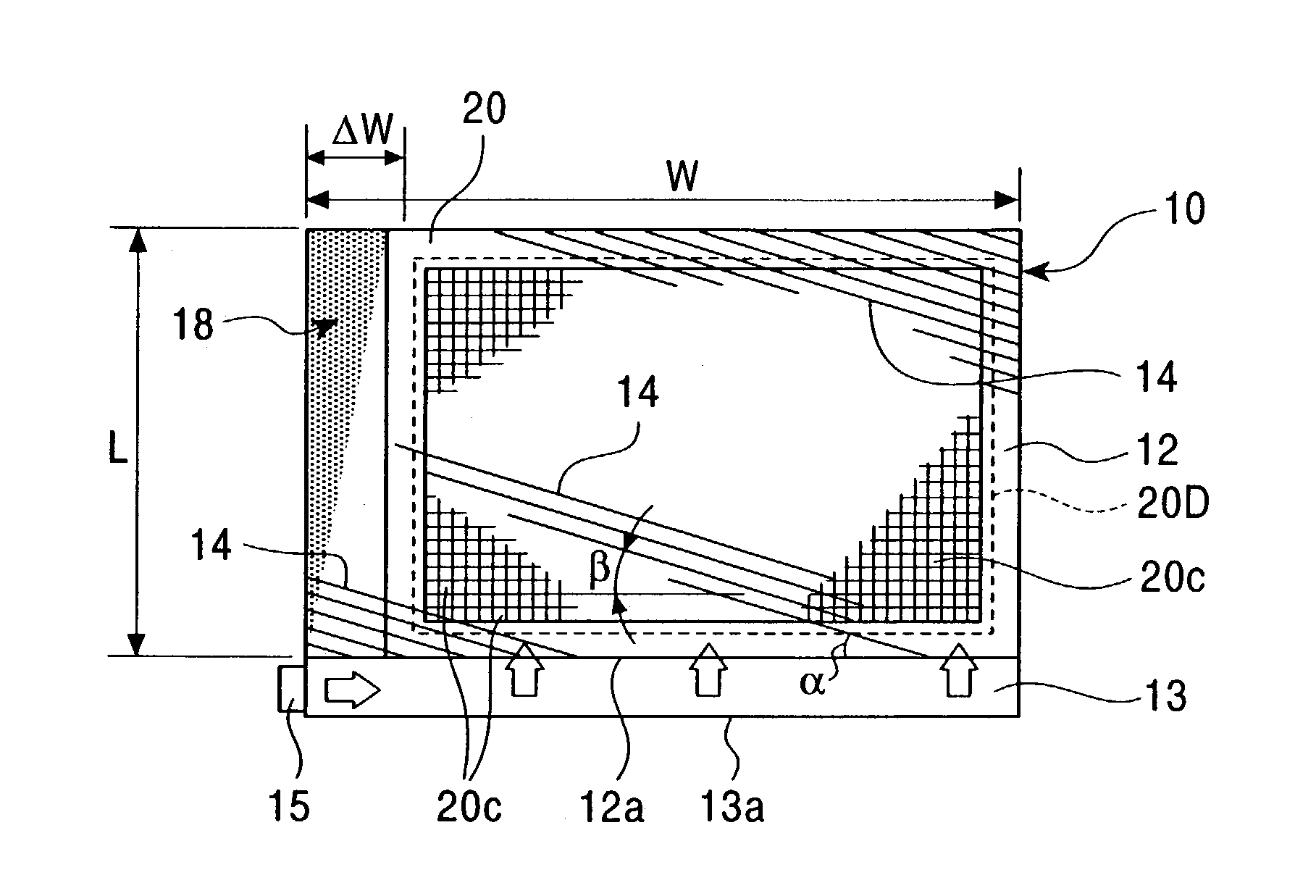
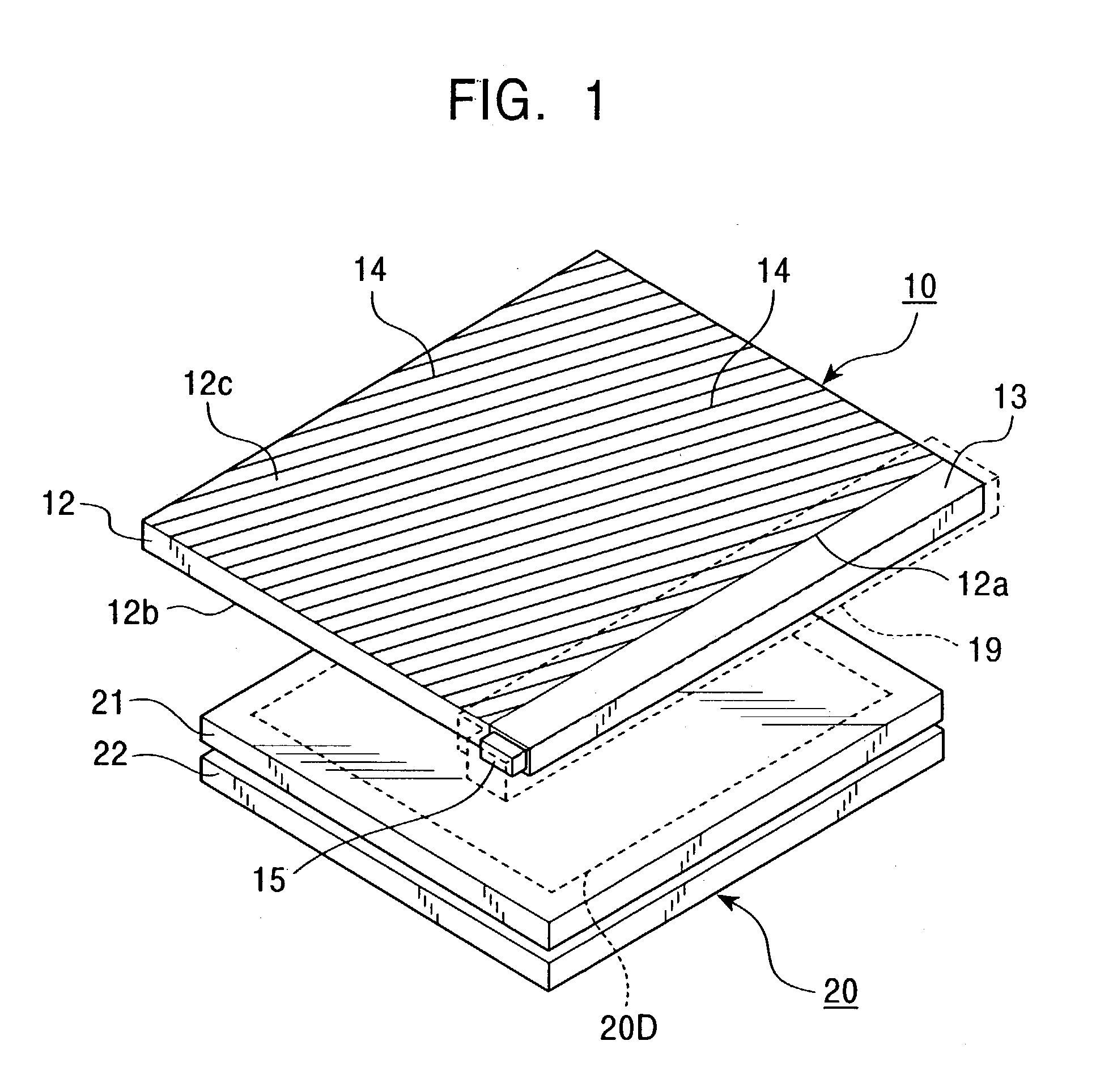
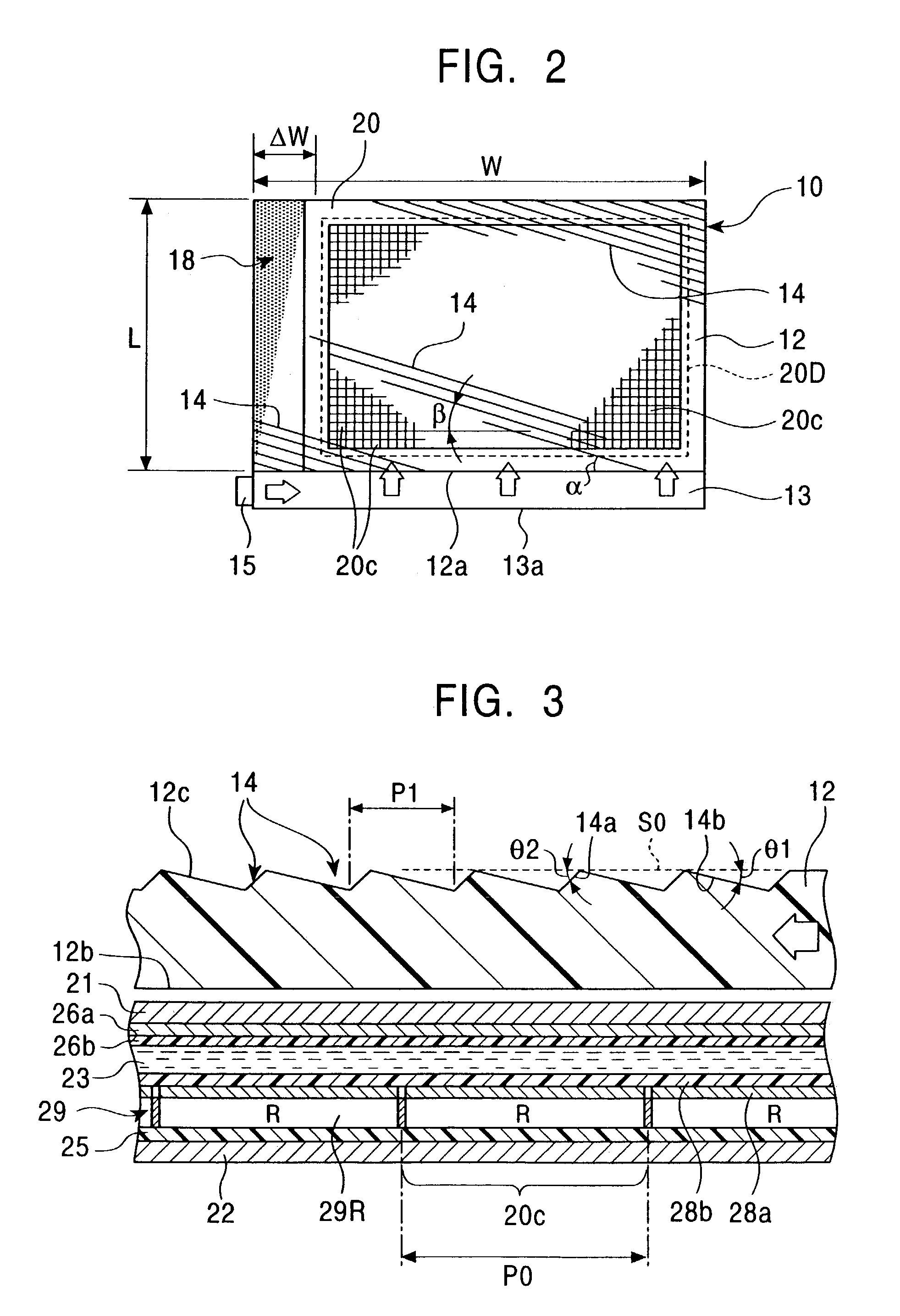
[0070]FIG. 1 is a perspective view illustrating the structure of a liquid crystal display device according to a first embodiment of the present invention, and FIGS. 2 and 3 are respectively a plan view and a sectional view illustrating the structure of the liquid crystal display device shown in FIG. 1. As shown in FIGS. 1 to 3, the liquid crystal display device according to the first embodiment is formed of a front light (an illumination device) 10 and a liquid crystal display unit 20 disposed behind the front light 10 (at the lower side in the figure).

[0071]As shown in FIG. 1, the front light 10 is formed of a substantially flat light guiding plate 12, an intermediate light guide 13 disposed on a side surface 12a of the light guiding plate 12, a light emitting element 15 disposed on one end surface of the intermediate light guide 13, a casing (a light shield) 19 disposed so as to cover the intermediate light guide 13, the light emitting element 15, and a part of the light guiding p...

second embodiment

[0142]FIG. 19 is a plan view illustrating the structure of a front light 40 according to a second embodiment of the present invention. The front light 40 shown in this figure is formed of a light guiding plate 42, an intermediate light guide 43 having an L-shape in plan view and disposed along two side surfaces 42a and 42b of the light guiding plate 42, and a light emitting element 45 disposed on an end surface of the intermediate light guide 43.

[0143]The light guiding plate 42 has substantially the same flat shape as that of the light guiding plate 12 according the first embodiment shown in FIGS. 1 to 3, and has a plurality of prismatic grooves 44, formed parallel to each other in plan view, on one side thereof and a flat surface on the other side thereof. Thus, light incident on the two side surfaces 42a and 42b is reflected at the prismatic grooves 44 and is then emitted as illumination light. The prismatic grooves 44 are formed at an oblique angle with respect to the side surfac...

third embodiment

[0146]FIG. 20 is a plan view illustrating the structure of a front light 50 according to a third embodiment of the present invention. The front light 50 shown in this figure is formed of a light guiding plate 52, a rod-shaped intermediate light guide 53 disposed along a side surface 52a of the light guiding plate 52, and a light emitting element 55 disposed on one end surface of the intermediate light guide 53. The front light 50 according to the third embodiment contains a light guiding plate 52 that has a side surface 52b close to the light emitting element 55 and a reflective film 57, made from a highly-reflective metal thin film composed of Al, Ag, or the like, formed on the side surface 52b.

[0147]The light guiding plate 52 has substantially the same flat shape as that of the light guiding plate 12 according the first embodiment shown in FIGS. 1 to 3, and has a plurality of prismatic grooves 54, formed parallel to each other in plan view, on one side thereof and a flat surface ...


PUM


Abstract

An illumination device is constructed such that light illuminated by a light emitting element and transmitted through one side surface of a light guiding plate via an intermediate light guide is introduced into the light guiding plate and the light propagating in the light guiding plate is emitted from an output surface of the light guiding plate so as to illuminate a liquid crystal display unit (an illumination object) disposed behind the light guiding plate, such that a part of the light guiding plate, through which the liquid crystal display unit is displayed in a transmissive manner, serves as a display area, and such that the light guiding plate is formed so as to extend beyond the display area of the liquid crystal display unit and towards the light emitting element, along the longitudinal direction of the intermediate light guide.

Description

[0001]This application claims the benefit of priority to Japanese Patent Application JP2002-029731,filed on Feb. 6, 2002.BACKGROUND OF THE INVENTION[0002]1. Field of the Invention[0003]The present invention relates to illumination devices and liquid crystal display devices, and more particularly, it relates to an illumination device which uniformly and brightly illuminates a large area with a single light source, and also to a liquid crystal display device using the same.[0004]2. Description of the Related Art[0005]A conventional front light of a liquid crystal display device has a unit structure including a light source, an intermediate light guide, a light guiding plate, and a casing integrally holding these components and having a reflective inner surface.[0006]FIG. 21A is a perspective view illustrating the structure of such a liquid crystal display device and FIG. 21B is a plan view illustrating the structure of the liquid crystal display device shown in FIG. 21A. The liquid cr...

Claims


Application Information

Patent Timeline
IPC IPC(8): F21V7/04G02F1/1335G02B6/00F21V8/00F21Y101/02G02F1/13357
CPCG02B6/0018G02B6/0028G02B6/0038G02B6/0036G02B6/0031G02F1/1335
Inventor SUGIURA, TAKUROOHIZUMI, MITSUO
Owner ALPS ALPINE CO LTD
Learn More