
Luggage storage structure for automobile and lifter

Inactive Publication Date: 2007-02-20
FUJI JUKOGYO KK
View PDF16 Cites 22 Cited by
  • Summary
  • Abstract
  • Description
  • Claims
  • Application Information

AI Technical Summary

Benefits of technology

[0013]Another object of the present invention is to enhance the transfer flexibility of a plate member by transferring the plate member not only in the vertical direction but in the horizontal direction.
[0118]According to the present invention, in addition to the above function, each slider is separately controlled so as to reduce the load of one electric motor and increase the luggage capacity of the plate member.

Problems solved by technology

In other words, the luggage storage structure cannot keep the luggage secret.
Moreover, when a thief or the like smashes the key and sneaks to the vehicle, the exposed luggage cannot be secured.
In the above lifter, however, because the plate member transfers just upwardly and downwardly, the lifter cannot be disposed therein unless the vertical stroke of the plate member is secured.
In other words, the lifter has a drawback of being unavailable, for example, in a narrow space sloped in an upper position, such as a loft of a house and a trunk room of the automobile.
Both cases undermine a transfer capability for the luggage.
Like this, because the transfer direction of the plate member is limited to just upwardly and downwardly, the lifter is quite inconvenient for practical uses.

Method used


Image

  • Luggage storage structure for automobile and lifter
  • Luggage storage structure for automobile and lifter
  • Luggage storage structure for automobile and lifter

Examples


first embodiment

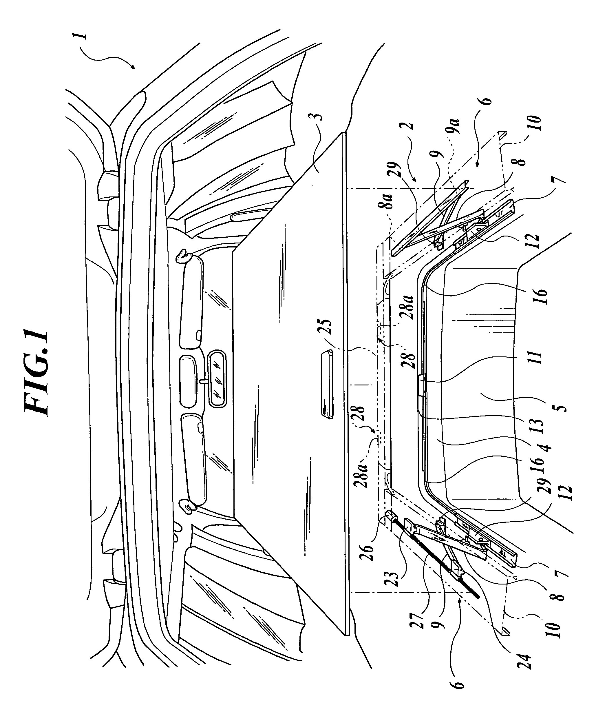
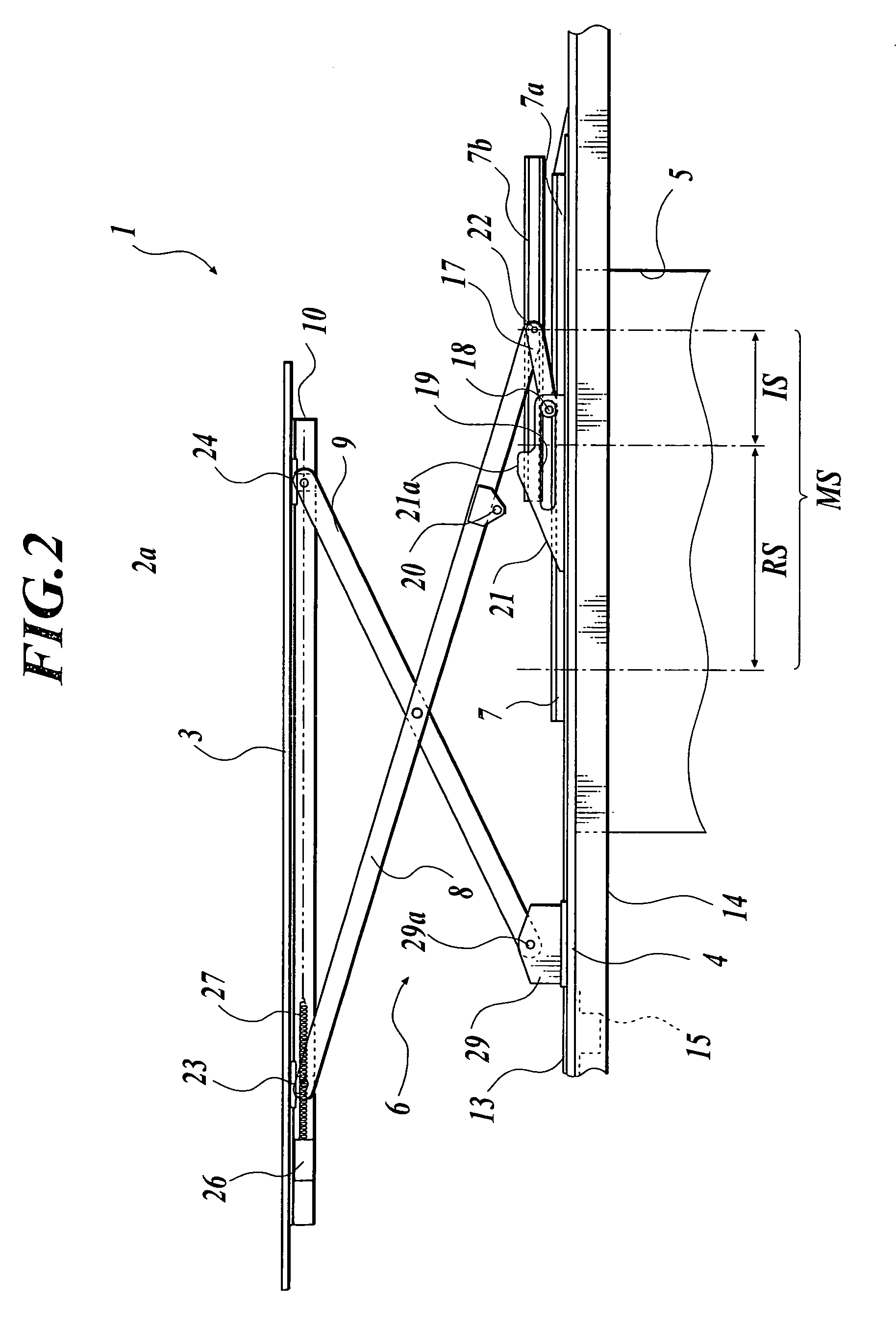
[0143]FIGS. 1 to 10 show one embodiment of the present invention. FIG. 1 is perspective view of an inside of a vehicle and a lifter. FIG. 2 is a schematic side view of a luggage storage structure and the lifter of an automobile. FIG. 3 is the schematic side view of the luggage storage structure and the lifter of the automobile. FIG. 4 is the schematic side view of the luggage storage structure and the lifter of the automobile. FIG. 5 is a partially outside explanatory view of the luggage storage structure and the lifter of the automobile. FIG. 6 is a front sectional view of a rail frame. FIG. 7 is an exploded perspective view of a slider. FIG. 8 is the front sectional view of a plate member frame. FIG. 9 is the perspective view showing a lower surface of a plate member. FIG. 10 is an outside perspective view showing a table for supporting a plate member by a leg device for the table and a folding chair that is raised.

[0144]As shown in FIG. 1, the luggage storage structure and the li...

second embodiment

[0209]FIGS. 15 to 19 show a second embodiment of the present invention. FIG. 15 is an externally perspective view inside the vehicle. FIG. 16 is a side view of the luggage storage structure of an automobile. FIG. 17 is a plan view of the luggage storage structure of an automobile. FIG. 18 is a front sectional view of the plate member frame. FIG. 19 is a side sectional view in the vicinity of the aperture which is formed on the plate member for grasping by hand.

[0210]As shown in FIG. 15, the luggage storage structure for this automobile transfers approximately up and down a plate member 303 disposed in a luggage space 302 of the vehicle 301. The plate member 303 approximately closes an upper part of a storage concave portion 305 formed so as to project downward on a floor panel 304. In other words, the plate member 303 is a bottom of the luggage space 302 when being lowered. The plate member 303 opens the storage concave portion 305 and approximately separates the luggage space 302 i...


PUM


Abstract

A luggage storage structure for an automobile includes: a storage concave portion formed so as to project downward on a floor panel and capable of storing luggage, a plate member for approximately closing an upper part of the storage concave portion, and a transfer mechanism for transferring the plate member approximately up and down in an upper part of the floor panel. The luggage structure is securely protected by the plate member and the transfer mechanism.

Description

BACKGROUND OF THE INVENTION[0001]1. Field of the Invention[0002]The present invention relates to a luggage storage structure for an automobile for storing a luggage in a storage concave portion formed in a floor panel, and a lifter for transferring a plate member for the luggage at least upwardly and downwardly.[0003]2. Description of Related Art[0004]Heretofore, as this type of luggage storage structure for an automobile, it is known that a tray for storing a luggage is disposed in a storage concave portion formed in a floor panel (For example, Japanese Patent Application Publication (Unexamined) Tokukaihei-2002-240634). The tray is structured so as to extend and contract in a horizontal direction and a length of the horizontal direction is changed in accordance with usage purposes. In this kind of the luggage storage structure, an upper part of the storage concave portion is open and the luggage is mounted and removed in any directions as required on the tray at any time.[0005]How...

Claims


Application Information

Patent Timeline
IPC IPC(8): B60P9/00B60P1/00B66F3/22B66F7/06B60R5/04B60R13/01B62D43/10B66F7/08
CPCB60R5/04B60R5/045B66F7/08B62D43/10B66F7/065B60R13/01
Inventor MASUDA, TOSHIOATAKE, ATSUSHIINOUE, MASAHIKO
Owner FUJI JUKOGYO KK
Learn More