

Piezoelectric element, liquid ejecting head and liquid ejecting apparatus
- Summary
- Abstract
- Description
- Claims
- Application Information
AI Technical Summary
Benefits of technology
Problems solved by technology
Method used
Image

Examples
Embodiment Construction
[0029]Hereinafter, the invention will be described in detail with reference to an exemplary embodiment of the present invention.
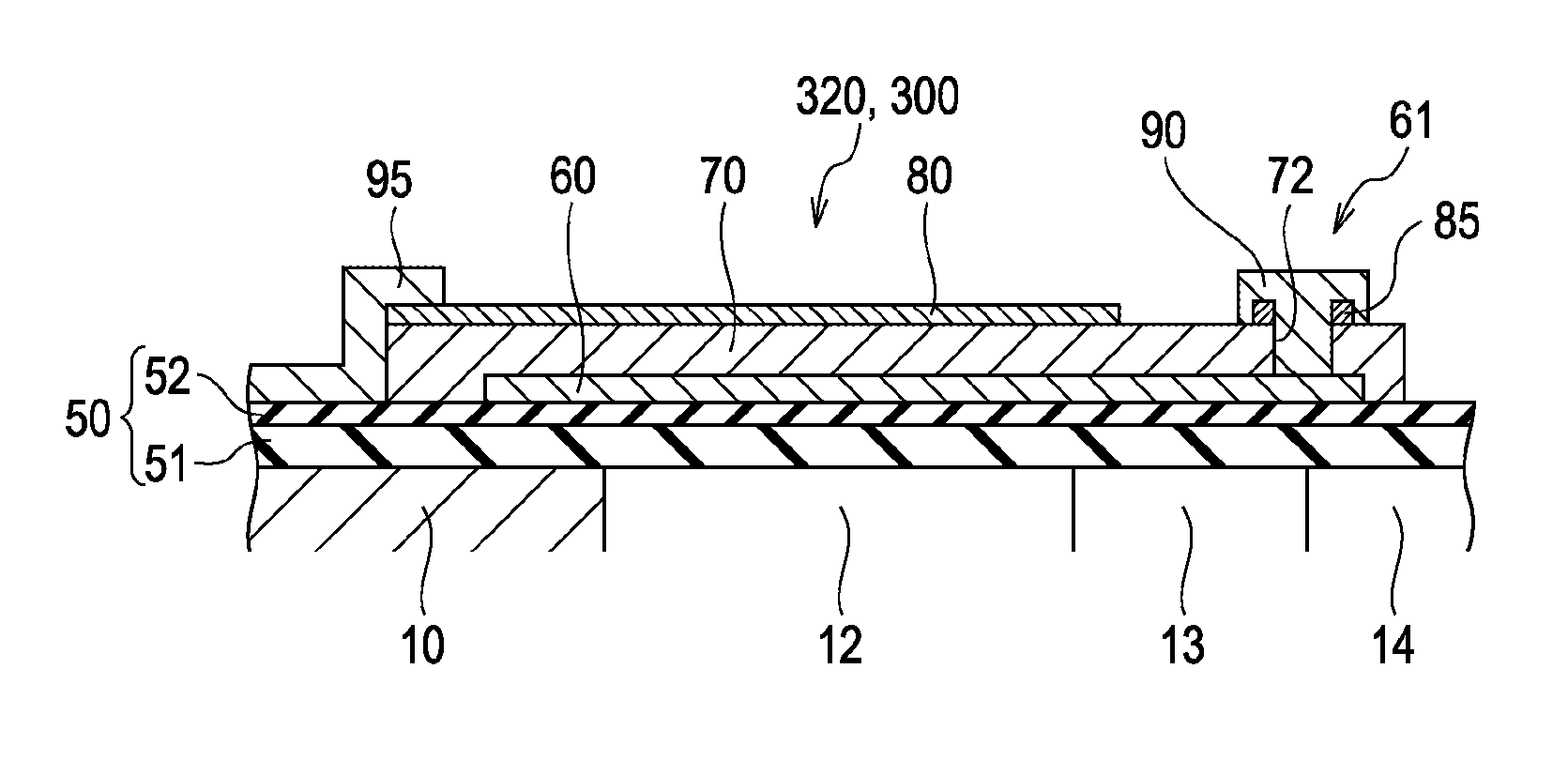
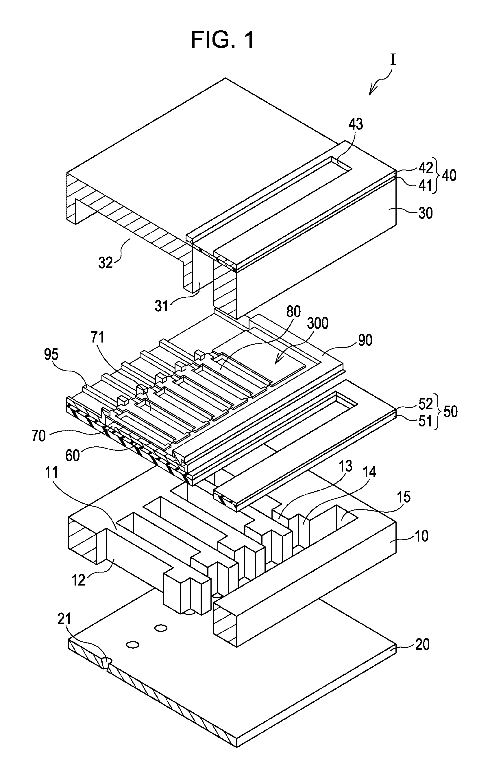
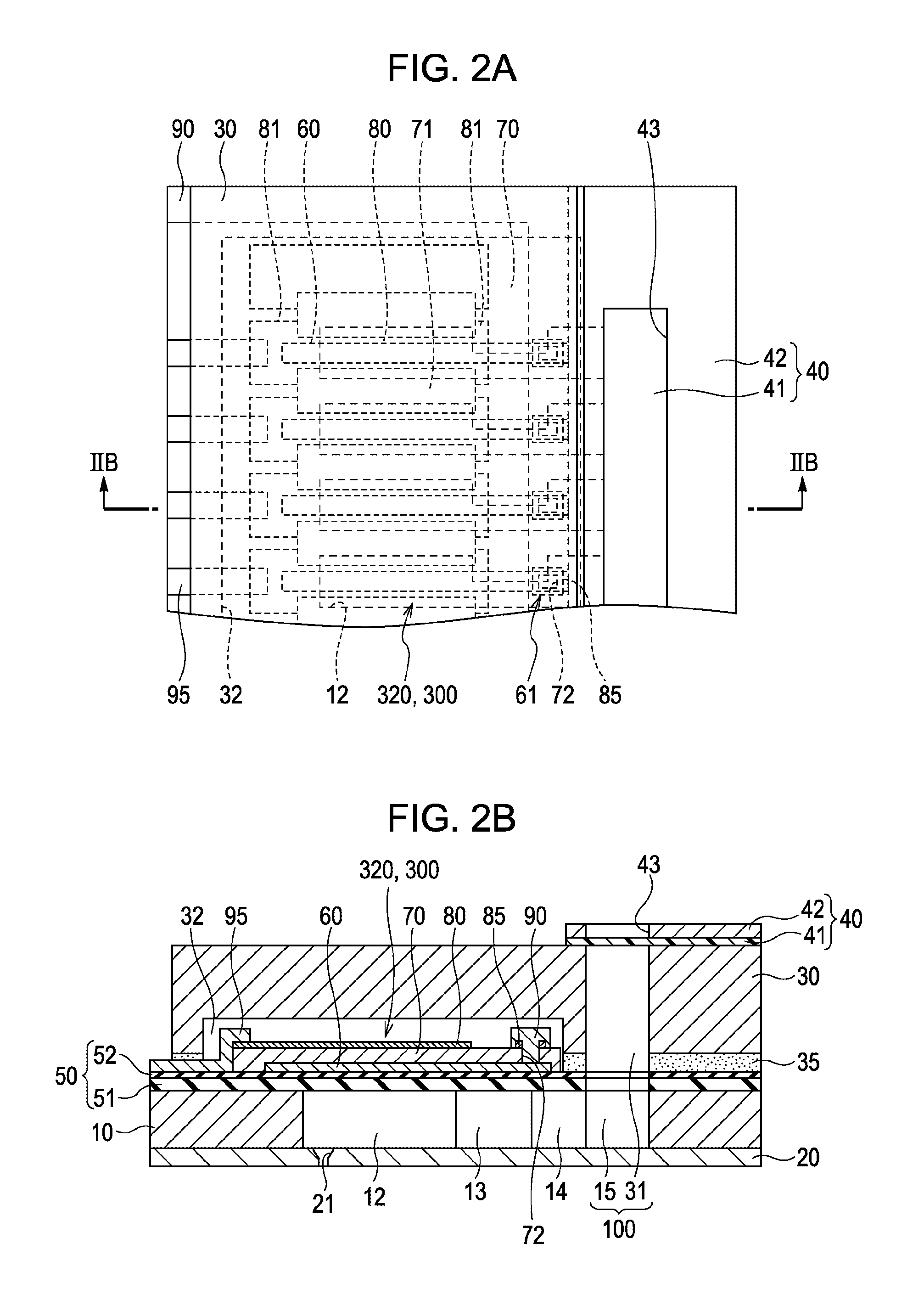
[0030]FIG. 1 is an exploded perspective view of an ink jet recording head which is an example of a liquid ejecting head according to an embodiment of the present invention, and FIG. 2A is a plan view of FIG. 1, and FIG. 2B is a cross-sectional view taken along line IIB-IIB in FIG. 2A.
[0031]As shown in the drawing, in a flow path forming substrate 10, pressure generation chambers 12 are provided side by side, which are partitioned by a plurality of partition walls 11 in the width direction (the lateral direction). Further, in one end side in the longitudinal direction of the pressure generation chamber 12 of the flow path forming substrate 10, an ink supply path 13 and a communication path 14 are partitioned by the partition wall 11. In addition, in one end of the communication path 14, a communication section 15 configuring a portion of a manifold 100 which...
PUM
 Abstract
Description
Claims
Application Information