
Rotor of rotary electrical machine

Active Publication Date: 2019-07-04
MITSUBISHI ELECTRIC CORP
View PDF9 Cites 0 Cited by
  • Summary
  • Abstract
  • Description
  • Claims
  • Application Information

AI Technical Summary

Benefits of technology

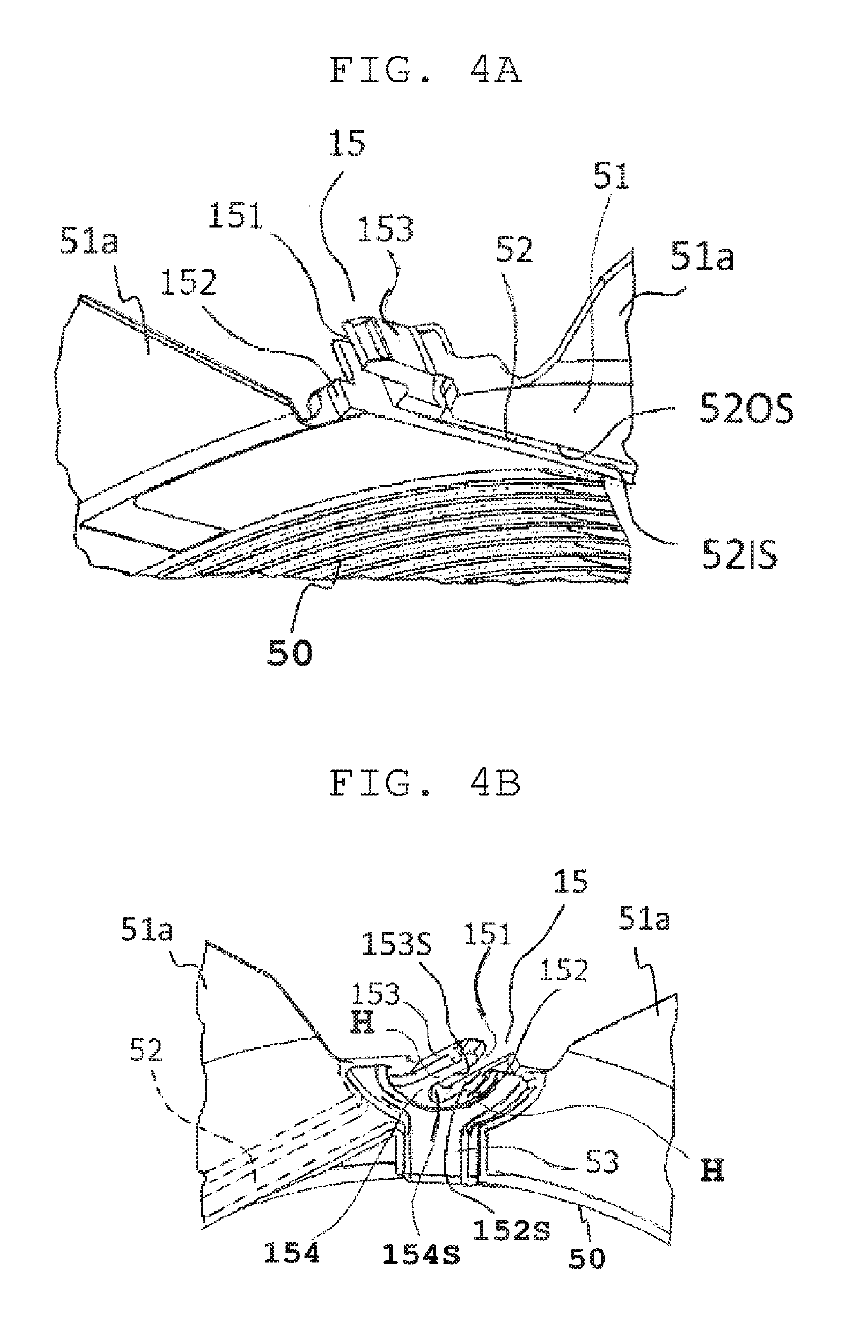
The invention provides a simplified and cost-effective way to improve the winding workability and electrical reliability of a rotary electrical machine. This is achieved by forming a winding-start receiving groove in the insulation bobbin and placing a holder on the flange, with a holder groove that extends at an angle relative to the radial direction of the insulation bobbin. This allows the winding-start lead wire of the field coil to be securely held, resulting in a more reliable and durable rotor for the rotary electrical machine.

Problems solved by technology

In the example of the rotor of the rotary electrical machine disclosed in patent document 1, end-twisting onto a coil lead wire securing portion is unnecessary but end-twisting onto the lead wire end twisting portion is needed so that damage to the wire and deformation of the wire unavoidably decrease mechanical strength.
Also, a decrease in winding workability due to the end-twisting step is still unavoidable.
Thus, the notch groove has such a serious disadvantage that in the worst case, part of the rotor around the notch groove as well as components to which the lead wire is connected may be broken.

Method used


Image

  • Rotor of rotary electrical machine
  • Rotor of rotary electrical machine
  • Rotor of rotary electrical machine

Examples


embodiment 1

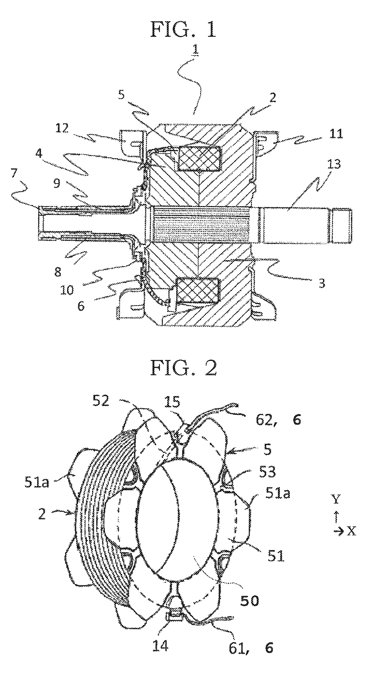
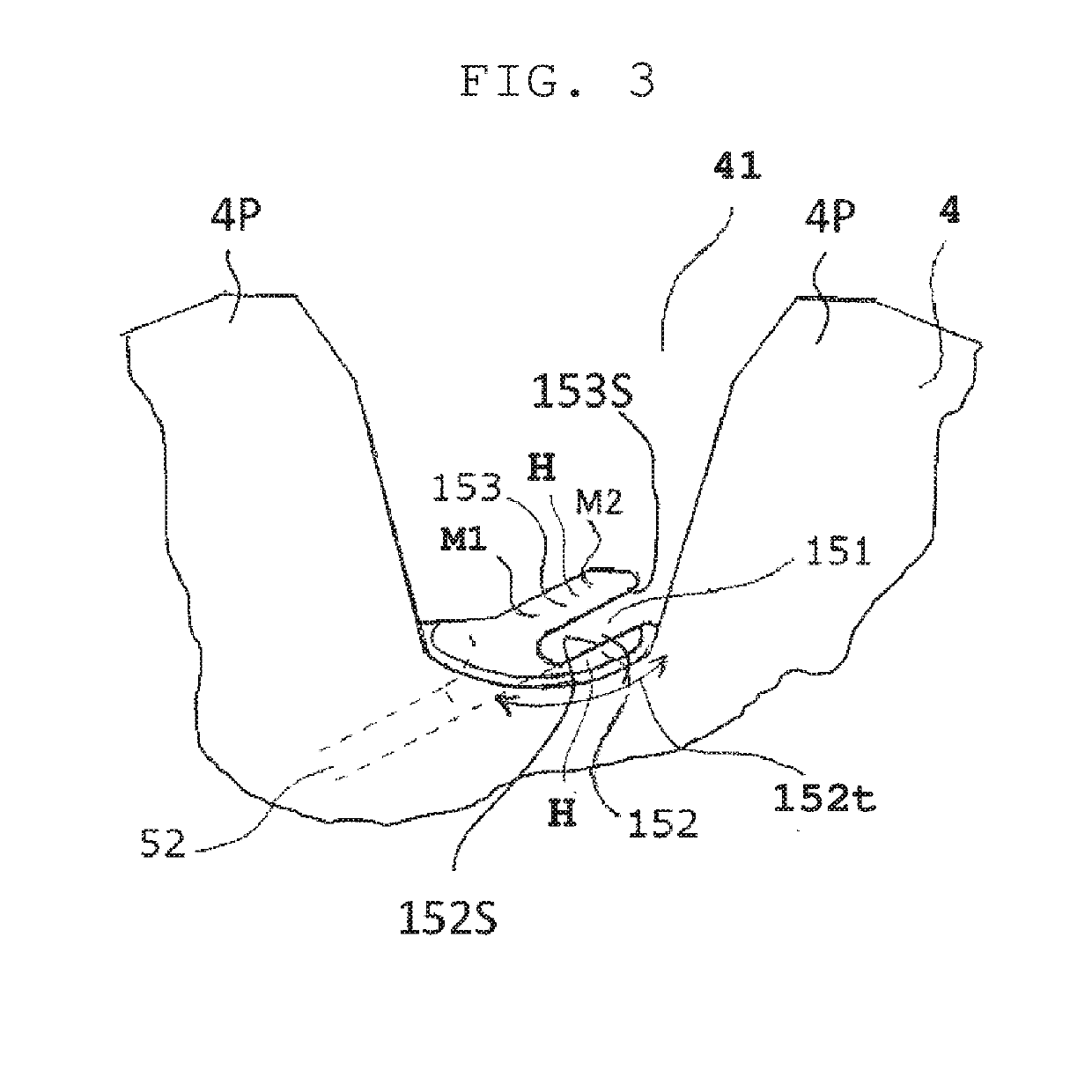
[0021]FIG. 1 is a cross-sectional view of a rotor of a rotary electrical machine according to embodiment 1 of the invention, illustrating a configuration of the rotor, and FIG. 2 is a perspective view of an insulation bobbin of the rotor in FIG. 1, and a field coil wound on the insulation bobbin. The rotor 1 of the rotary electrical machine includes the field coil 2 to generate a magnetic flux and a field core to cover the field coil 2. The field core includes a first field core body 3 and a second field core body 4, which include claw-shaped tarn poles (claw poles) arranged to mesh with each other. The field coil 2 is wound around a winding portion 50 of the insulation bobbin 5. A slip ring assembly 7 includes two slip rings to which a current is supplied from the outside through brushes, not illustrated.

[0022]A lead wire 6 drawn from the field coil 2 is arranged in such a manner that after the field coil 2 is wound on the winding portion 50 of the insulation bobbin 5, a terminal-e...

embodiment 2

[0042]As another embodiment, for example, a configuration in which the wire-holding function is enhanced, as illustrated in FIG. 7, may be considered. At least one small protrusion 152a and at least one small protrusion 153a are respectively formed on the radially outer surface 152S of the radially inner holder wall 152 and the radially inner surface 153S of the radially outer holder wall 153 to enhance the detachment preventing effect of the winding-start lead wire 62. Moreover, in the case of providing a plurality of small protrusions, as illustrated in FIG. 7, a desired wire-holding state in accordance with a wide variety of lead wire diameters is obtained to increase general versatility and common usability of the insulation bobbin.

[0043]That is, a technical feature of embodiment 2 lies in that the winding-start lead wire detachment preventing portion 152a, 153a to prevent detachment of the winding-start lead wire is integrally formed on at least one of the radially inner holder...


PUM


Abstract

A winding-start receiving groove in which a winding-start lead wire of a field coil is received is formed in an inner surface of a flange of an insulation bobbin. A holder is disposed on the flange and located on a radially outer side of the winding-start receiving groove. The holder is formed with a holder groove located on an extension line of the winding-start receiving groove and extending at an angle relative to a radial direction of the insulation bobbin. The winding-start lead wire of the field coil is received in the winding-start receiving groove and the holder groove and held by the holder. This makes it possible to obtain a rotor of a rotary electrical machine with a simplified configuration at low cost not only to improve winding workability but also to enhance electrical reliability and durability.

Description

BACKGROUND OF THE INVENTIONField of the Invention[0001]The present invention relates to a rotor of a vehicular alternating-current (AC) generator mounted as a rotary electrical machine on, for example, a vehicle, and driven by an engine of the vehicle to generate power and, in particular, relates to a configuration of an insulation bobbin on which a field coil of the rotor is wound.Description of the Related Art[0002]As an insulation bobbin of a field coil used for a rotor of a rotary electrical machine of the related art, an insulation bobbin is known in which a groove is formed in an inner surface of a side flange of a cylindrical portion on which a coil is wound, a winding-start lead wire of the field coil is inserted in this groove, and the field coil is regularly wound on the cylindrical portion. A lead wire end twisting portion to which an end of the winding-start lead wire inserted in the groove is secured is provided on an outer circumferential portion of the flange in close...

Claims


Application Information

Patent Timeline
IPC IPC(8): H02K3/52H02K3/32H02K1/24
CPCH02K3/528H02K3/325H02K1/243
Inventor SHIMIZU, SHINTAROMAEKAWA, KENJIISHIKAWA, TORUIMAZAWA, YOSHIRO
Owner MITSUBISHI ELECTRIC CORP
Learn More