

Hand accessory usable with an implement handle
a technology for hand accessories and implement handles, applied in golfing accessories, racket sports, protective garments, etc., to achieve the effect of enhancing the user's gripping and/or swinging strength
- Summary
- Abstract
- Description
- Claims
- Application Information
AI Technical Summary
Benefits of technology
Problems solved by technology
Method used
Image

Examples
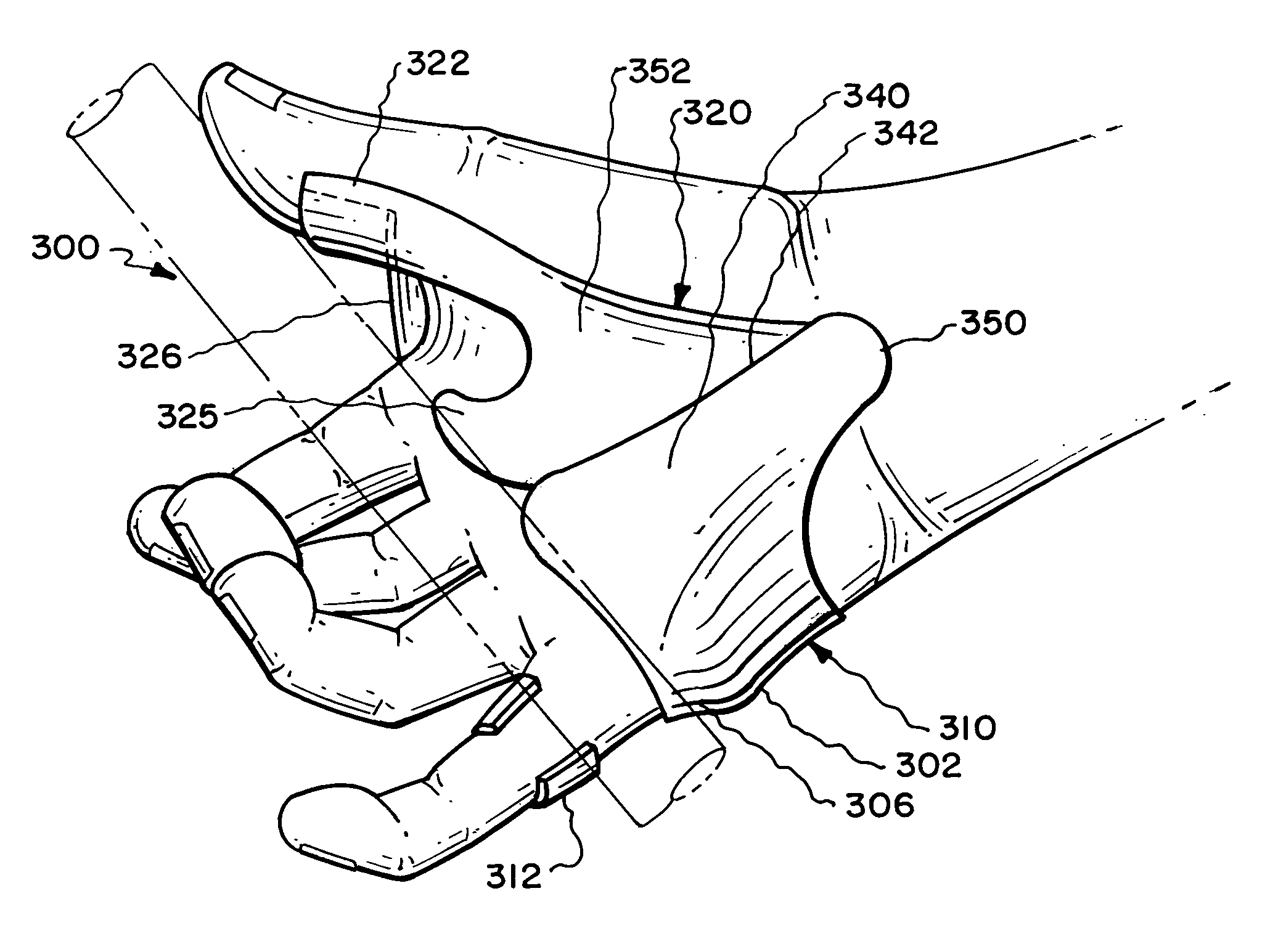
embodiment 300
[0093]Much of the structure of lifeline anchor 320 is thumb base wedge 352, which contours the thumb 44 with thin material extending upwardly from swivel 330 and inwardly from lifeline contact 324, thumb base wedge 352 resting against the hand's thumb bases 30 and 31, and extending upwardly to circular thumb attachment 322, thence extending to the back side of the hand to glove / web anchor 326 pressing into the top of the hand's upper web 46 (from the back side of the hand) and serving to locate and fix the hand accessory to a glove. Glove / web anchor 326 is constructed at such an angle as to create forward tension at thumb attachment 322 away from the hand's sensitive thumb bones 34 when glove / web anchor 326 is flexed slightly forward to its attachment area of a glove. Glove / web anchor 326 also may receive contact from recoiling handle 48 depending on the user's grip, but the great majority of energy is dissipated in the lower hand through structure in the lower areas of embodiment 3...
embodiment 203
[0099]The location and composition of lever 308 is critical to the success of direct contact stress absorption. If the pathway of lever 308 towards thumb base / wrist anchor 350 moves upwardly (as in embodiment 203) angling over tough ball 38 with too much thickness, even though a tough area, discomfort from direct pressure of handle 48 will occur. The pathway of lever 308 must be as low as possible while still reaching its junction with thumb base / wrist anchor 350 (also at the lowest point allowed by stress receiving area wrist hollow 75), such that lever 308 runs primarily along the bottom of tough ball 38 (not supported by tough ball 38) but supported by fulcrum platform 302 anchored at lower tough ball 39 and “locked” into fleshy relocation channel 309, actually serving to “widen” the hand. Refinement of portions of lever 308 make hand accessory 300 workable with all types of bottom hand gripping of a baseball bat and are further explained in a final paragraph on “bottom hand grip...
PUM
 Abstract
Description
Claims
Application Information