Wideband voltage controlled oscillator employing evanescent mode coupled-resonators

a voltage control and coupled-resonator technology, applied in the direction of oscillator, angle modulation by variable impedence, electrical apparatus, etc., can solve the problems of limiting or affecting the performance of the pll itself, affecting the performance of the device in which the pll is employed, and typically remaining bottlenecks in low phase noise, so as to achieve the effect of expanding the frequency of operation

Active Publication Date: 2007-02-20
SYNERGY MICROWAVE CORP
View PDF46 Cites 14 Cited by
  • Summary
  • Abstract
  • Description
  • Claims
  • Application Information

AI Technical Summary

Benefits of technology

[0034]Other aspects of the present invention include support of a uniform negative resistance over a wideband frequency range. In addition, the configuration may be further extended in a coupled ring form to extend the frequency of operation in an N-push / push-push approach.

Problems solved by technology

The dynamic operating range and noise performance of a VCO may limit or affect the performance of the PLL itself, which in turn may affect the performance of the device in which the PLL is employed, e.g., RF transceivers, cell phone, modem card, etc.
Despite the continuous improvement in VCO technology, low phase noise typically remains a bottleneck and poses a challenge to RF transceiver (transmitter—receiver) design.
This is typically considered due to the more demanding parameters of the VCO design: low phase noise, low power consumption and a wide frequency tuning range.
As the frequency for wireless communication shifts to higher and higher frequency bands, generation of an ultra-low noise, wideband, thermally stable and compact signal source at a relatively low cost becomes more and more challenging due to the frequency limitations of the active devices and broadband tunability of the tuning diode.
In the past, wide tuning range and good phase noise performance were generally considered to be opposing requirements due to the problem of the controlling the loop parameters and the dynamic loaded Q of the resonator over the range of wideband operation.
On the other hand, the requirements for low noise performance over the complete frequency range are typically demanding.

Method used


Image

  • Wideband voltage controlled oscillator employing evanescent mode coupled-resonators
  • Wideband voltage controlled oscillator employing evanescent mode coupled-resonators
  • Wideband voltage controlled oscillator employing evanescent mode coupled-resonators

Examples


Embodiment Construction

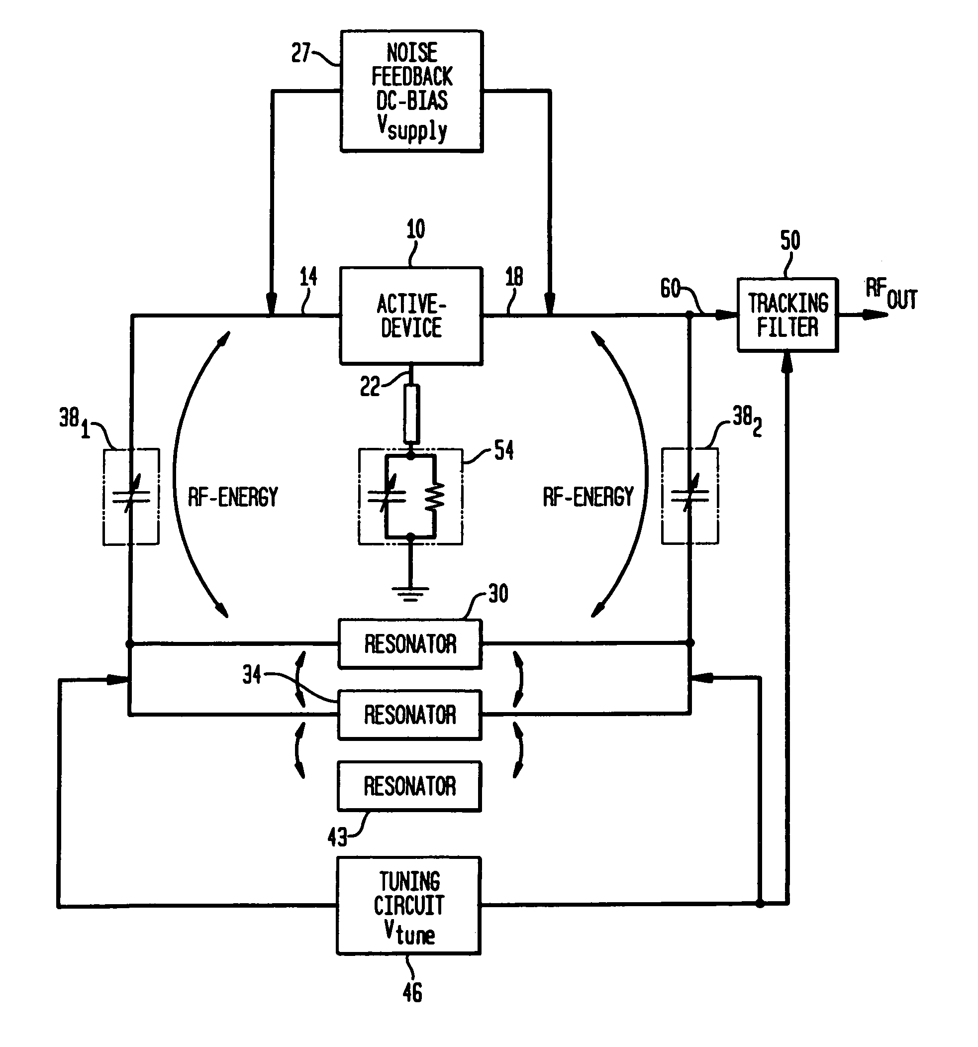
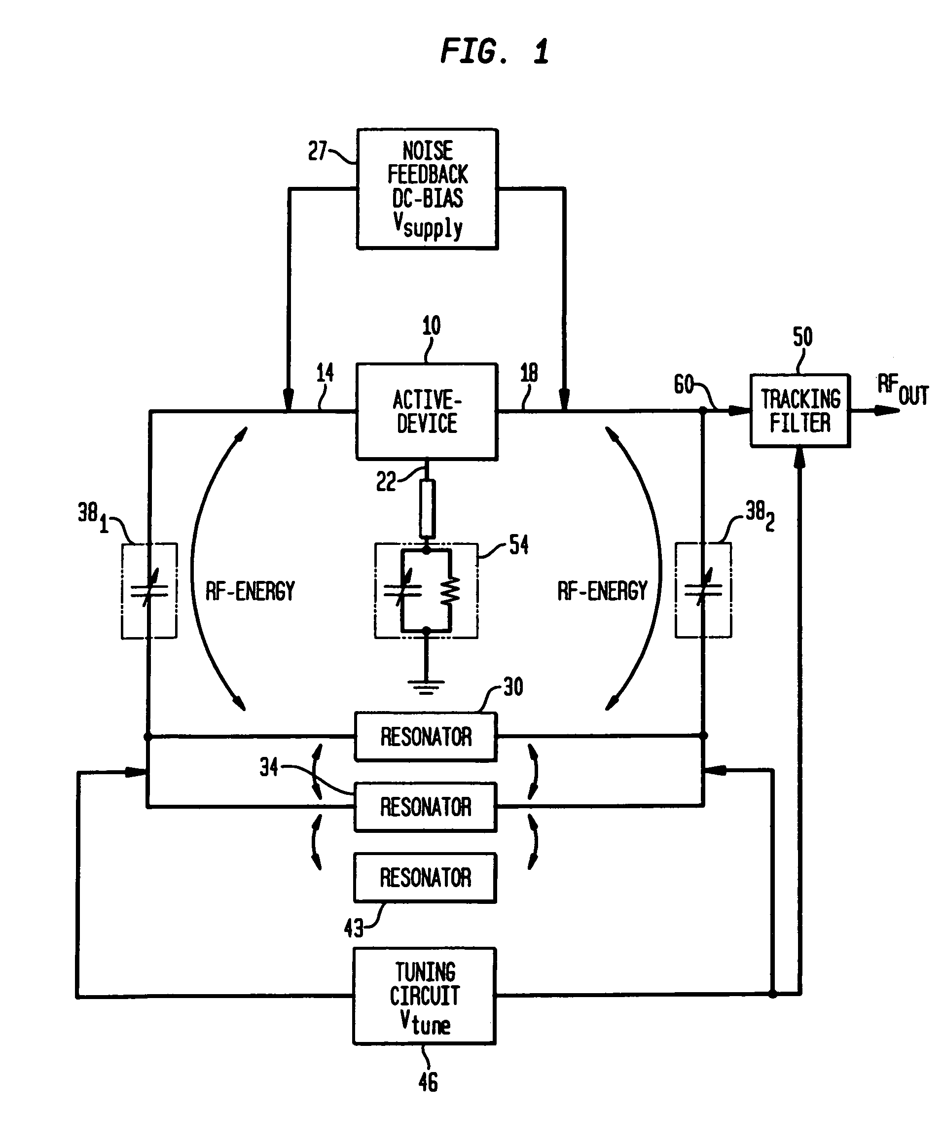
[0044]FIG. 1 is a block diagram illustrating a voltage controlled oscillator (VCO) 1 in accordance with an aspect of the present invention. Voltage controlled oscillator 1 includes an active device 10 having first, second and third terminals, 14, 18 and 22, respectively. Active device 10 may comprise a transistor element wherein the first, second and third terminals, 14, 18 and 22, respectively comprise the base, collector and emitter terminals of the transistor element. More specifically, active device 10 may comprise a bipolar or FET transistor, including any MOS or GaAs active three terminal device. Active device 10 may also include any three terminal device that is operable to provide a 180 degree phase shift between at least two terminals of the device.

[0045]Noise feedback and DC-bias circuitry 27 is coupled between the first and second terminals, 14 and 18. Noise feedback and DC bias circuitry 27 supplies a DC voltage to the device 10 and feeds back a select amount of phase no...


PUM


Abstract

In one aspect, the present invention includes a voltage controlled oscillator comprising an active device having a plurality of resonators coupled across two terminals of the device and at least one resonator coupled across the plurality of resonators. The at least one resonator preferably operates as an evanescent mode buffer capable of storing a select amount of energy present in the oscillator.

Description

CROSS-REFERENCE TO RELATED APPLICATIONS[0001]This application claims the benefit of the filing date of U.S. Provisional Patent Application No. 60 / 564,173, filed Apr. 21, 2004, the disclosure of which is hereby incorporated herein by reference.BACKGROUND OF THE INVENTION[0002]A voltage controlled oscillator (VCO) or oscillator is a component that can be used to translate DC voltage into a radio frequency (RF) voltage or signal. In general, VCOs are designed to produce an oscillating signal at a particular frequency ‘f’ that corresponds to a given tuning voltage. In particular, the frequency of the oscillating signal is dependent upon the magnitude of a tuning voltage Vtune applied to a tuning diode network across a resonator circuit. The frequency ‘f’ may be varied from fmin to fmax and these limits are referred as the tuning range or bandwidth of the VCO. The tuning sensitivity of the VCO is defined as the change in frequency over the tuning voltage and it is desirable to tune the V...

Claims


Application Information

Patent Timeline
Patent Type & Authority Patents(United States)
IPC IPC(8): H03B5/18
CPCH03B5/1852H03B5/1847
Inventor ROHDE, ULRICH L.REBEL, REIMUNDPODDAR, AJAY KUMAR
Owner SYNERGY MICROWAVE CORP
Why Eureka
Try Eureka