EMI filter and frequency filters having capacitor with inductance cancellation loop

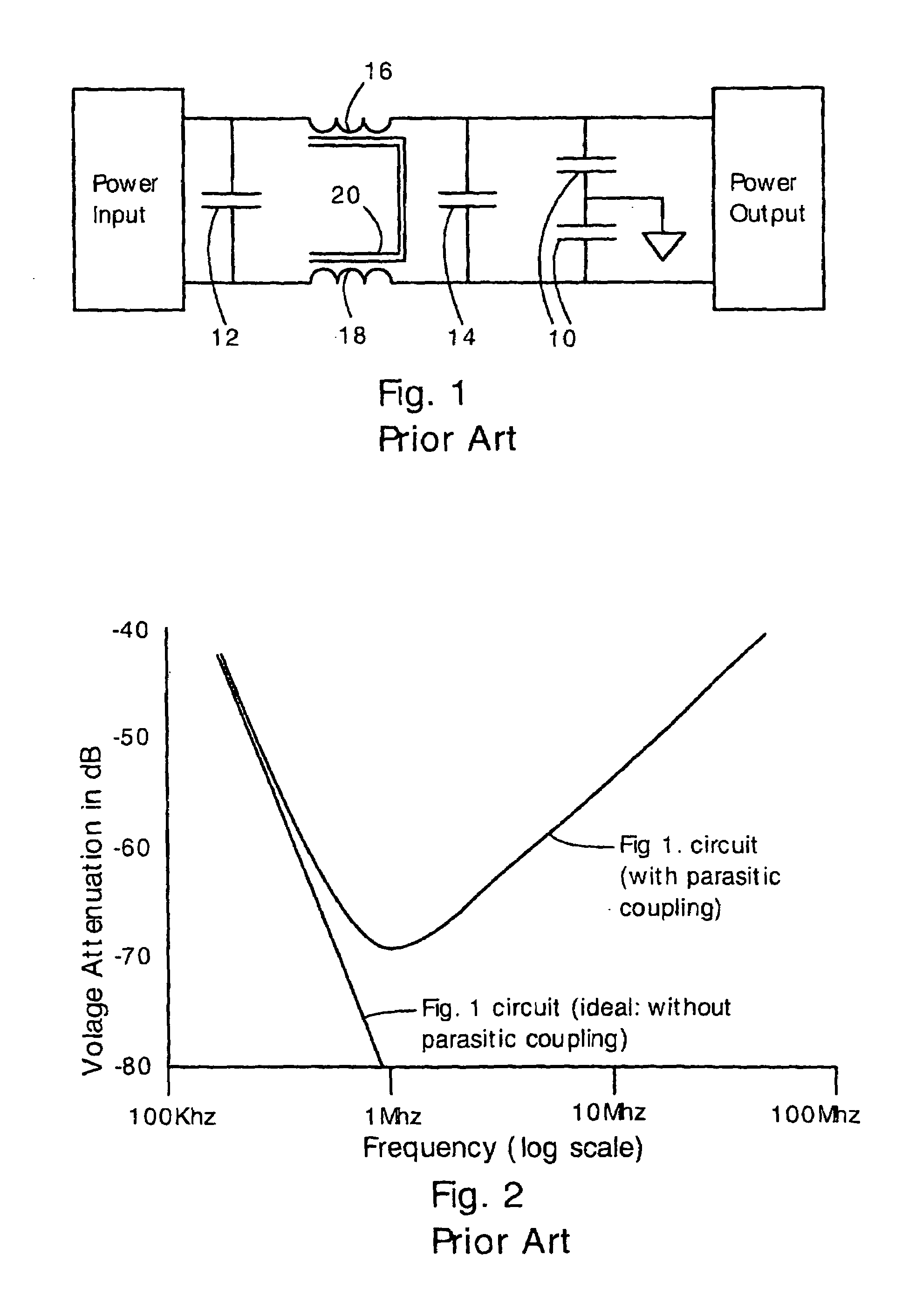
a capacitor and inductance cancellation technology, applied in the field of electromagnetic interference filters, can solve the problems of reducing the attenuation of the filter with increasing frequency, affecting the performance of the filter, and particularly affecting the frequency range of about 1–30 mhz, and achieve the effect of high attenuation of high frequency signals

Inactive Publication Date: 2007-02-20
VIRGINIA TECH INTPROP INC
View PDF8 Cites 24 Cited by
  • Summary
  • Abstract
  • Description
  • Claims
  • Application Information

AI Technical Summary

Benefits of technology

[0013]A second inductor can be provided coupled to the first inductor. Both inductors can be oriented horizontally with respect to a circuit board so that inductive coupling between the inductors and circuit board traces is reduced.
[0017]The present filter circuit can be an EMI filter, a band pass filter, a low pass filter, or a band reject filter. All these filters will have high attenuation of unwanted high frequency signals.
[0020]In the present invention, the combination of inductance cancellation loop and horizontally oriented inductors provides exceptionally high attenuation of high frequency signals.

Problems solved by technology

Noise in the frequency range of about 1–30 Mhz is particularly problematic because it can propagate across a circuit board via inductive coupling.
A problem with the circuit of FIG. 1 is that the attenuation of the filter decreases with increasing frequency.
This degradation in filter performance occurs because of parasitic inductive coupling (i.e., mutual inductance) between filter components.
The parasitic inductive couplings cause an enormous degradation in filter performance that increases with increasing frequency.
With modern electronics operating at ever-increasing speeds and ever-decreasing voltages, it is becoming more difficult to protect sensitive circuits from damaging and disruptive electrical noise.

Method used


Image

  • EMI filter and frequency filters having capacitor with inductance cancellation loop
  • EMI filter and frequency filters having capacitor with inductance cancellation loop
  • EMI filter and frequency filters having capacitor with inductance cancellation loop

Examples


Embodiment Construction

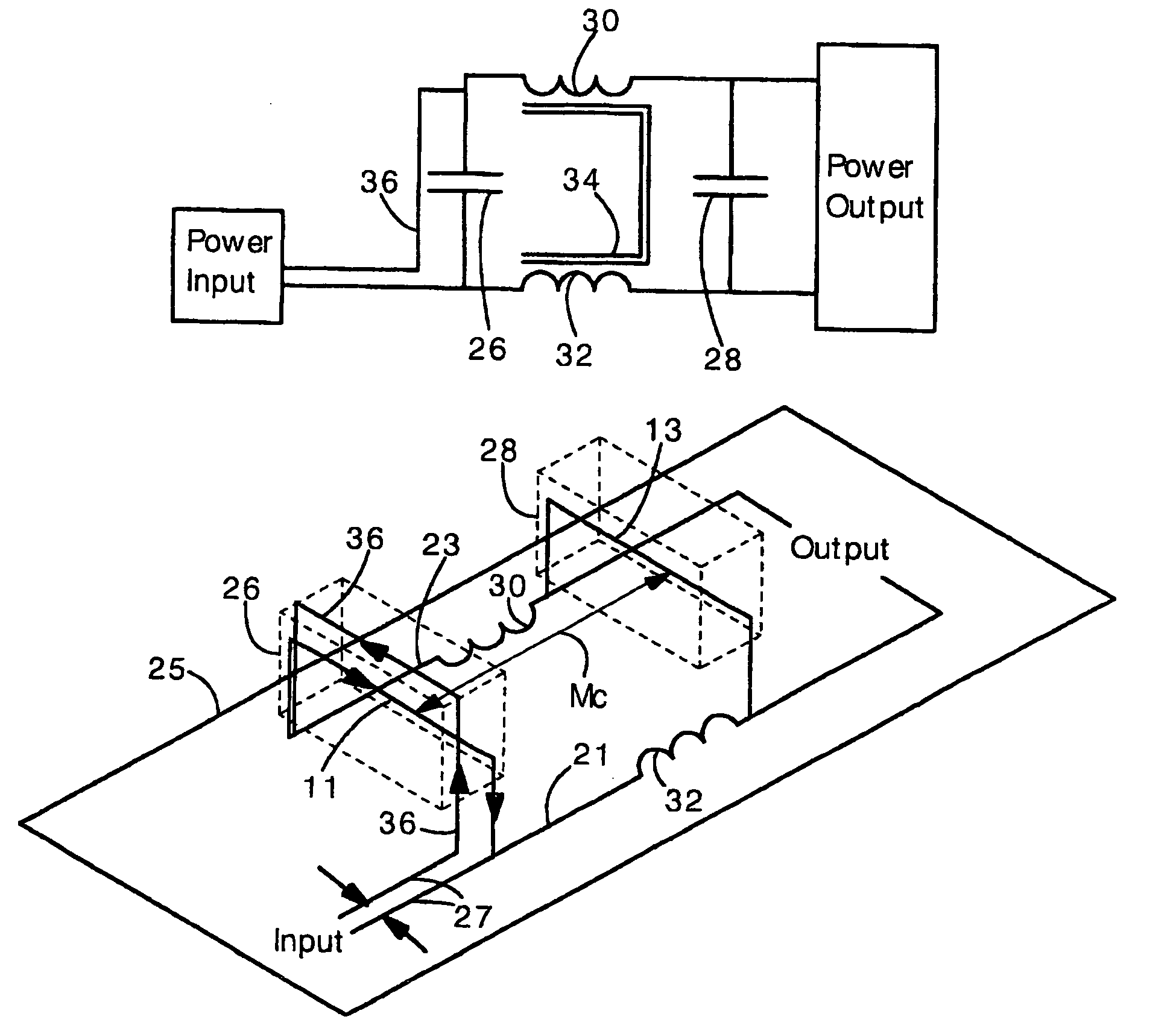
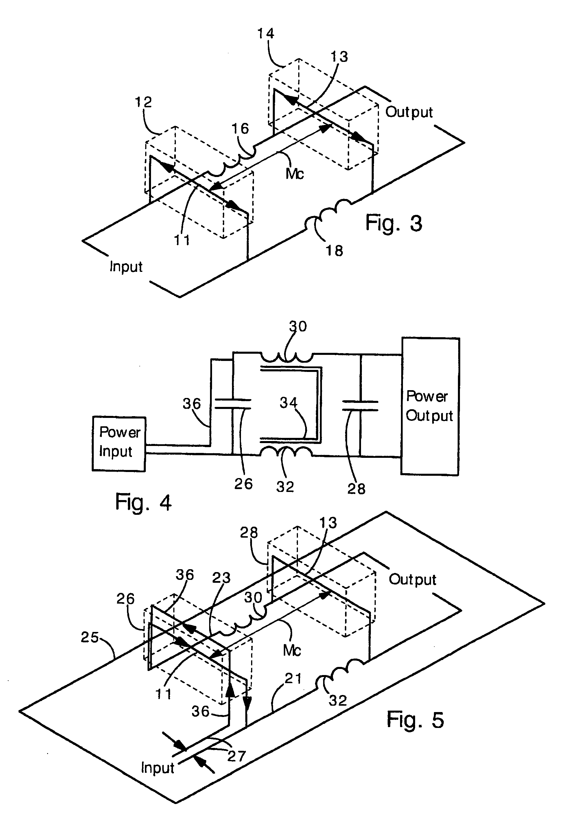
[0038]The present invention provides electromagnetic interference (EMI) filters and frequency filters (e.g., high or low pass filtering, band pass or band reject filtering) having a capacitor with an inductive cancellation loop. The inductive cancellation loop is connected to the capacitor and provides a current flow that is anti-parallel to current flowing in the capacitor. The loop greatly reduces the mutual inductance between the capacitor and other filter components. Preferably, the inductive cancellation loop is in close proximity to the capacitor (e.g., the loop can be disposed on the capacitor). With the present inductive cancellation loop, the EMI filter has a much greater attenuation at high frequencies. Also, the present invention includes filters with inductors oriented horizontally with respect to a circuit board or circuit board traces. Horizontal orientation reduces coupling between leakage inductance and circuit board traces and between leakage inductance and capacito...


PUM


Abstract

An electromagnetic interference (EMI) filter or frequency filters (e.g. bandpass or band reject filters) in which a capacitor has an inductance cancellation loop. Inductive coupling between capacitors can allow undesired high frequencies to propagate across a filter. This is particularly a concern when the capacitors are oriented in parallel. In the present invention, the inductance cancellation loop is disposed adjacent to one capacitor so that mutual inductance between the capacitors is reduced. The attenuation of the filter at high frequencies is thereby increased. The loop can increase voltage attenuation of an EMI filter by about 20 dB. In another aspect, inductors in the filter are oriented horizontally relative to a circuitboard. Horizontal orientation reduces leakage inductance coupling between the inductors and circuitboard traces, and between the inductor and capacitors, thereby preventing unwanted propagation of high frequencies. Both measures in combination can provide a voltage attenuation increase of 30 dB.

Description

[0001]This invention was made with the assistance from a grant by the National Science Foundation (EEC-973677), and the U.S. Government may have certain rights in this invention.FIELD OF THE INVENTION[0002]The present invention relates generally to electromagnetic interference (EMI) filters. More specifically, the present invention relates to an EMI filter with a capacitor having an extra current loop for canceling parasitic inductive coupling between capacitors. With the inductive coupling between capacitors weakened, the EMI filter provides an exceptionally high attenuation.BACKGROUND OF THE INVENTION[0003]Electromagnetic interference (EMI) filters are commonly used throughout the electronics industry. EMI filters are typically placed on input power lines of electronic equipment so that high frequency electromagnetic noise does not enter or escape the equipment.[0004]It is desirable for EMI filters to attenuate high frequency noise as much as possible. Typically, noise that must b...

Claims


Application Information

Patent Timeline
Patent Type & Authority Patents(United States)
IPC IPC(8): H03H7/09
CPCH04B3/28H03H7/427H03H7/1758H03H7/1775H03H2001/005H03H7/1766H03H7/175
Inventor WANG, SHUOLEE, FRED C.ODENDAAL, WILLIEM GERHARDUS
Owner VIRGINIA TECH INTPROP INC
Why Eureka
Try Eureka