Device and a method for electrical coupling

a technology of electrical coupling and electrical coupling device, which is applied in the direction of electrically conductive connections, electrical apparatus, and inductance, etc., can solve the problems of easy variation, difficult penetration, and axial positioning of pipe sections relativ

Inactive Publication Date: 2005-03-31
VETCO GRAY CONTROLS
View PDF4 Cites 18 Cited by
  • Summary
  • Abstract
  • Description
  • Claims
  • Application Information

AI Technical Summary

Benefits of technology

[0008] The object of the present invention is to provide a device for achieving electrical coupling between a first and a second pipe section mechanically coupled to each other, which makes it possible to transmit electric power and / or signals between electrical equipment in a first part of a wellbore and electrical equipment in a second part of the wellbore.

Problems solved by technology

A problem of conveying power and signals arises when the pipe comprises two or more pipe sections mechanically coupled to each other and it is desired to install instrumentation in the lower part of the well.
It is thus difficult to penetrate it with the necessary electrical wiring for the well instrumentation installed in the lower part of the well.
Another difficulty arising in connection with coupling of electrical power and signals between pipe sections comprising a PBR and seal stem is that the axial positioning of the pipe sections relative to each other may easily vary within + / − 1 meter.
At present if well instrumentation is to be installed in the lower part of is the well, the whole pipe has to be installed in one pass, as there is no way for making electrical connections between two pipe sections downhole.

Method used


Image

  • Device and a method for electrical coupling
  • Device and a method for electrical coupling
  • Device and a method for electrical coupling

Examples


Embodiment Construction

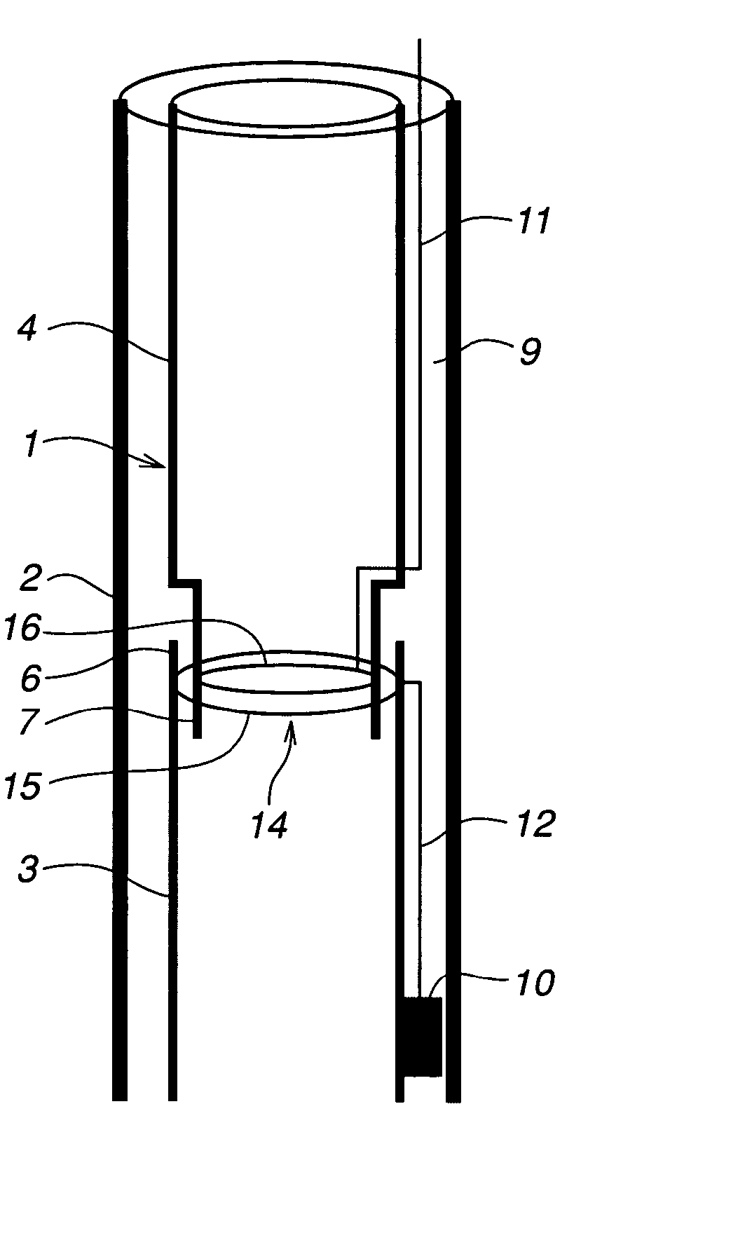
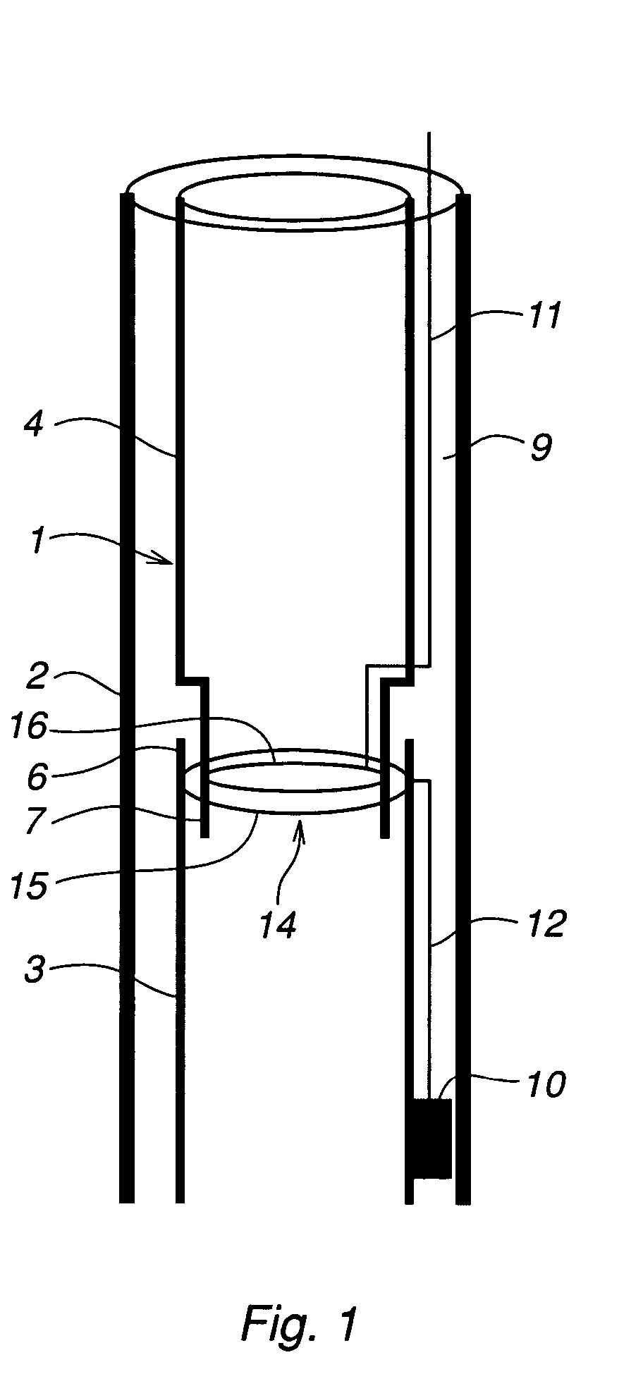
[0023]FIG. 1 shows a sub sea well for production of oil and / or gas comprising two concentric pipes, an inner pipe 1, called a production tubing, and an outer pipe 2, called a production casing, surrounding the inner pipe 1. The inner pipe 1 comprises a first pipe section 3 and a second pipe section 4 arranged on top of the first pipe section 3. The first pipe section 3 comprises an upper end part 6 adapted for mechanical coupling to a lower end part 7 of the second pipe section 4. The end part 7 of the second pipe section is tapering, and has a smaller diameter than the remaining of the pipe section 4, and forming a so called seal stinger. The end part 6 of the first pipe section 3 has a larger diameter than the end part 7 of the second end section 4. The end part 6 is adapted for receiving the end part 7 and thus achieving a mechanical coupling between the pipe sections. The end part 6 forms a so called “Polished Bore Receptacle” (PBR), corresponding to the seal stinger. When the e...


PUM

PropertyMeasurementUnit
lengthaaaaaaaaaa
lengthaaaaaaaaaa
frequencyaaaaaaaaaa

Abstract

A device for electrical coupling between a first (3) and a second (4) pipe section mechanically coupled to each other and forming a pipe adapted for transportation of a fluid. The first pipe section comprises a first electric winding (15) and the second pipe section comprises a second electric winding (16). Said first and second windings are adapted for inductive coupling between the first and the second pipe section.

Description

FIELD OF THE INVENTION [0001] The present invention relates to a device for achieving electrical coupling between a first and a second pipe section mechanically coupled to each other and forming a pipe adapted for transportation of a fluid. The invention also relates to the use of such a device in an oil or gas well. [0002] The invention further relates to a method for transferring electric power and / or sensor signals between a first and a second pipe section mechanically coupled to each other and forming a pipe adapted for transportation of a fluid. [0003] The device and method are particularly suitable for down-hole applications in any oil field, off-shore as well as on land, including multilateral wells with chokes or instrumentation in the branches. PRIOR ART [0004] A well for production of oil and / or gas typically comprises two concentric pipes, an outer pipe (production casing) and an inner pipe (production tubing). A fluid, typically oil mixed with water, gas and sand, flows ...

Claims


Application Information

Patent Timeline
Patent Type & Authority Applications(United States)
IPC IPC(8): E21B17/02H01F38/14
CPCH01F38/14E21B17/028E21B17/0285E21B17/0283
Inventor ERIKSSON, KLASHAHEIM, SVEINHOSETH, JACOB G.HANSSON, PEDERYAGHMAI, SOHRAB
Owner VETCO GRAY CONTROLS
Why Eureka
Try Eureka