Electrochromic-nanoparticle displays

a technology of electron microparticles and display screens, applied in the field of display screens, can solve the problems of long image quality, insufficient service life of these displays, and particle size ranges that generally do not efficiently scatter incident light, and achieve the effect of changing the optical characteristic of the display

Inactive Publication Date: 2007-02-20
E INK CORPORATION
View PDF79 Cites 277 Cited by
  • Summary
  • Abstract
  • Description
  • Claims
  • Application Information

AI Technical Summary

Benefits of technology

[0020]In another aspect, this invention provides a method for operating a display, this method comprising providing first and second electrodes spaced from one another; providing a plurality of electrochromic nanoparticles disposed between the first and second electrodes, each of the nanoparticles having an electron-rich state and an electron-depleted state, the two states differing in at least one optical characteristic; and injecting charge from at least one of the first and second electrodes into the nanoparticles, and thereby causing at least some of the nanoparticles to switch between their electron-rich and electron-depleted states, thus changing an optical characteristic of the display.

Problems solved by technology

Such unencapsulated displays typically have problems with their long-term image quality which have prevented their widespread usage.
For example, particles that make up such electrophoretic displays tend to cluster and settle, resulting in inadequate service-life for these displays.
Particles in this size range do not generally scatter incident light efficiently unless they are concentrated.
The large-scale result is that the display darkens.
Such metal-oxide electrochromic displays are relatively slow because of the time for ion diffusion.
One disadvantage of electrochromic polymers is that optical densities tend to be lower than those of electrochromic metal oxide.

Method used


Image

  • Electrochromic-nanoparticle displays
  • Electrochromic-nanoparticle displays
  • Electrochromic-nanoparticle displays

Examples


Embodiment Construction

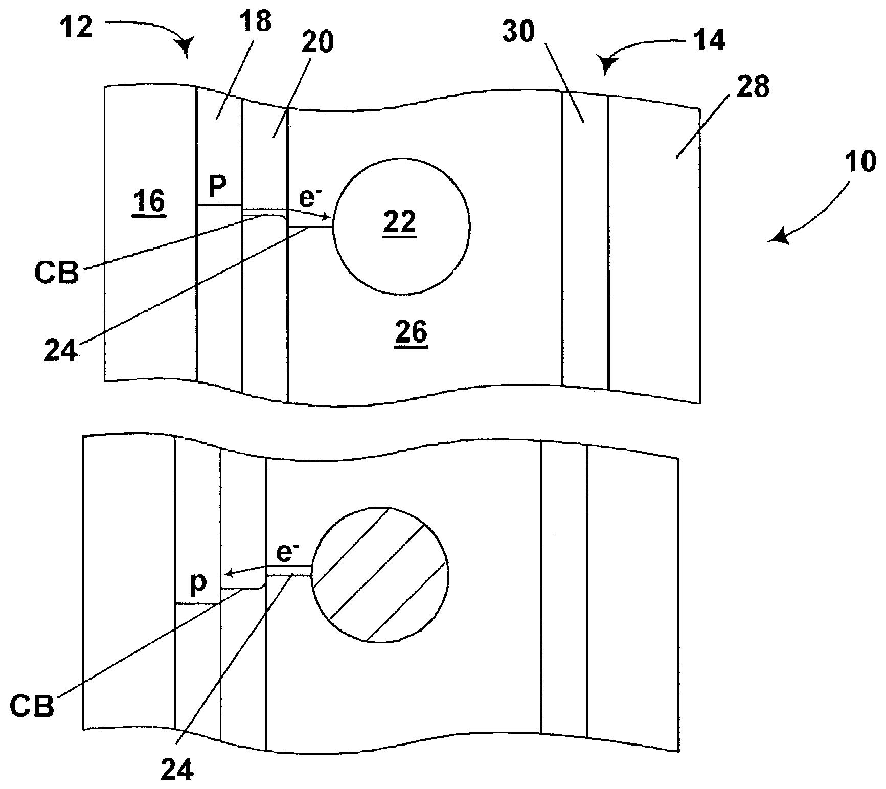
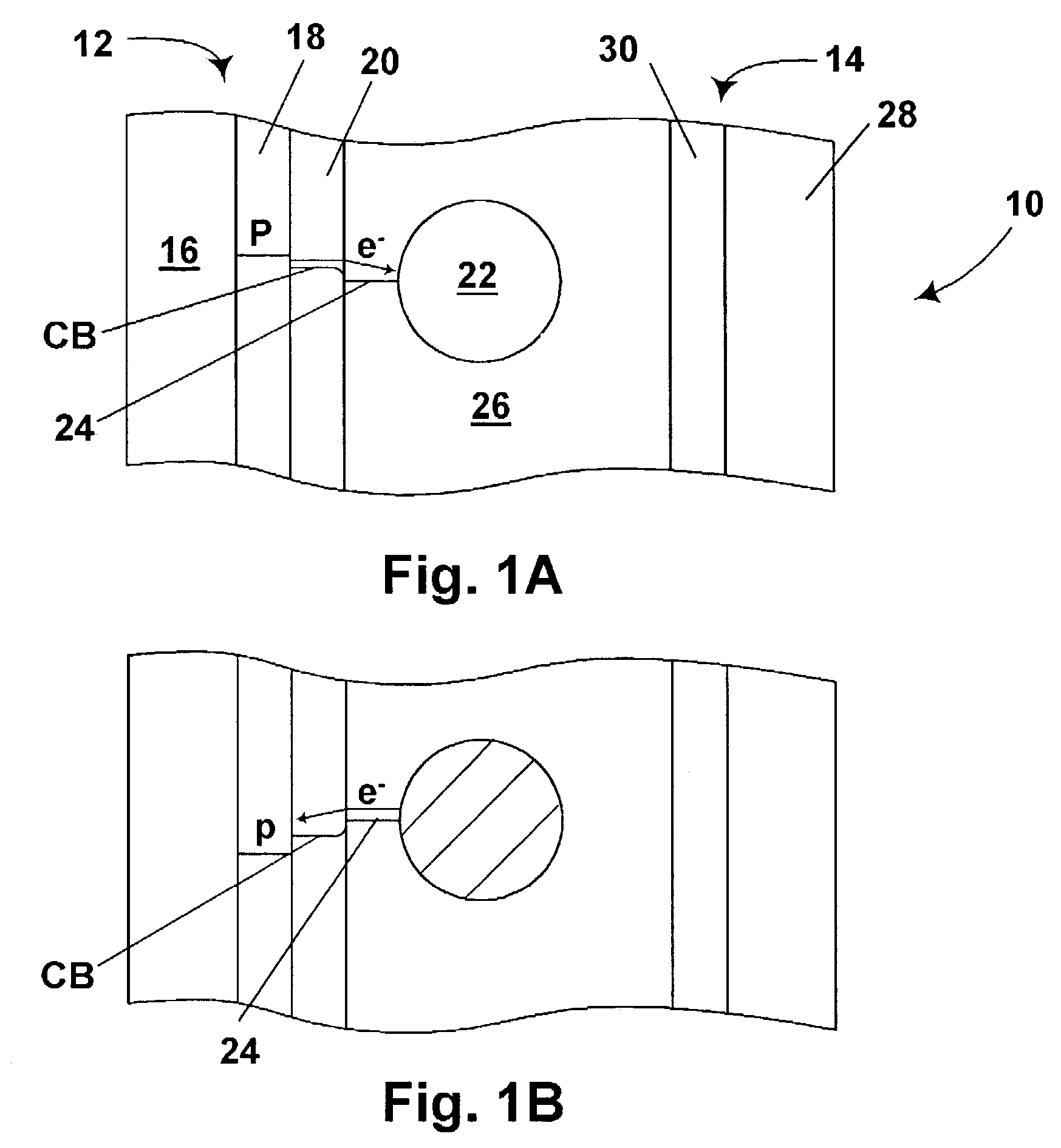
[0024]As already mentioned, the display of the present invention comprises first and second electrodes and a plurality of electrochromic nanoparticles disposed between these electrodes. Each of the nanoparticles has an electron-rich state and an electron-depleted state, and these two states differ in at least one optical characteristic; this optical characteristic can be any of those previously mentioned, and need not imply a difference between the two states in color visible to the human eye, although this is the most common optical characteristic. Injection of charge from at least one of the electrodes causes at least some of the nanoparticles to switch between their electron-rich and electron-depleted states, thus bringing about a change in the optical characteristic of the display.

[0025]Typically, the first and second electrodes of the present display will be in the form of parallel plates, at least one of which is substantially transparent, but it is not essential that the elec...


PUM

PropertyMeasurementUnit
diametersaaaaaaaaaa
diametersaaaaaaaaaa
diameteraaaaaaaaaa

Abstract

A display comprises spaced first and second electrodes, and a plurality of electrochromic nanoparticles disposed between the electrodes, each of the nanoparticles having an electron-rich state and an electron-depleted state, the two states differing in at least one optical characteristic. Upon injection of charge from one of the electrodes, the nanoparticles switch between their electron-rich and electron-depleted states, thus changing an optical characteristic of the display.

Description

CROSS REFERENCE TO RELATED APPLICATIONS[0001]This Application is a divisional of application Ser. No. 09 / 683,035, filed Nov. 12, 2001 now U.S. Pat. No. 6,580,545, which claims priority from Provisional Application Ser. No. 60 / 284,912, filed Apr. 19, 2001.REFERENCED APPLICATIONS[0002]This application is also related to: (1) application Ser. No. 09 / 565,417, filed May 5, 2000 (now U.S. Pat. No. 6,323,989; (2) application Ser. No. 10 / 054,721, filed Nov. 12, 2001 (now U.S. Pat. No. 6,538,801), a continuation-in-part of the aforementioned application Ser. No. 09 / 565,417, and (3) application Ser. No. 60 / 350,735, filed Nov. 12, 2001.BACKGROUND OF INVENTION[0003]The present invention relates to a display which uses electrochromic nanoparticles.[0004]Electrophoretic displays have been the subject of intense research and development for a number of years. Such displays use a display medium comprising a plurality of electrically charged particles suspended in a fluid. Electrodes are provided ad...

Claims


Application Information

Patent Timeline
Patent Type & Authority Patents(United States)
IPC IPC(8): G02F1/153G02F1/167G02F1/1503
CPCB82Y20/00G02F1/1523G02F2202/36G02F1/167G02F2001/1678G02F1/1503
Inventor MORRISON, IAN D.JACOBSON, JOSEPH M.
Owner E INK CORPORATION
Why Eureka
Try Eureka