Reconfigurable arrays with multiple unit cells

a technology of reconfigurable arrays and unit cells, applied in the direction of individual energised antenna arrays, antennas, electrical apparatus, etc., can solve the problems of increased power demands and costs, power consumption, and required feeding networks, and achieve the effect of changing their electromagnetic behavior

Active Publication Date: 2021-02-23
FLORIDA INTERNATIONAL UNIVERSITY
View PDF2 Cites 0 Cited by
  • Summary
  • Abstract
  • Description
  • Claims
  • Application Information

AI Technical Summary

Benefits of technology

[0004]Embodiments of the subject invention provide novel and advantageous arrays that are deployable and can change their electromagnetic behavior by changing their shape. The arrays can steer the beam using folding techniques and / or can achieve multiple operation states by folding the structure. The arrays can fold and unfold using any suitable actuation system known in the art (e.g., a motor or robotics). An array can include a foldable (e.g., an origami pattern) substrate with one or more antenna elements (e.g., an antenna element in each unit cell) disposed thereon. The foldable substrate can have predefined folding lines (e.g., folding lines for mountain- and / or valley-style folds) and / or hinges such that the foldable substrate can be folded into at least one particular predetermined shape in each folded state and can lay flat in an unfolded state. In a folded state, a first plurality of unit cells is visible from above the array and can be configured to steer in a particular first direction and / or operate at a particular first frequency. In the unfolded state a second plurality of unit cells (of a quantity greater than the first plurality of unit cells), and also possibly the first plurality of unit cells, are visible from above the array and can be configured to steer in a particular second direction and / or operate at a particular second frequency. The first direction can be different from the second direction and / or the first frequency can be different from the second frequency. In some embodiments, the first direction can be the same as the second direction or the first frequency can be the same as the second frequency. This concept can be extended to more than one folded state. The antenna elements and / or unit cells can have any suitable shape; for example, the unit-cell elements can have a rectangular, square, triangular, or circular lattice.

Problems solved by technology

Typically, to steer the beam in different directions complicated feeding networks are required, such as beamformers.
In the case of space applications, the most critical factors are reliability, cost, and power consumption.
Even though these classical beamsteering techniques are reliable, the complexity of their designs is significantly high, resulting to increased power demands and cost.

Method used


Image

  • Reconfigurable arrays with multiple unit cells
  • Reconfigurable arrays with multiple unit cells
  • Reconfigurable arrays with multiple unit cells

Examples


Embodiment Construction

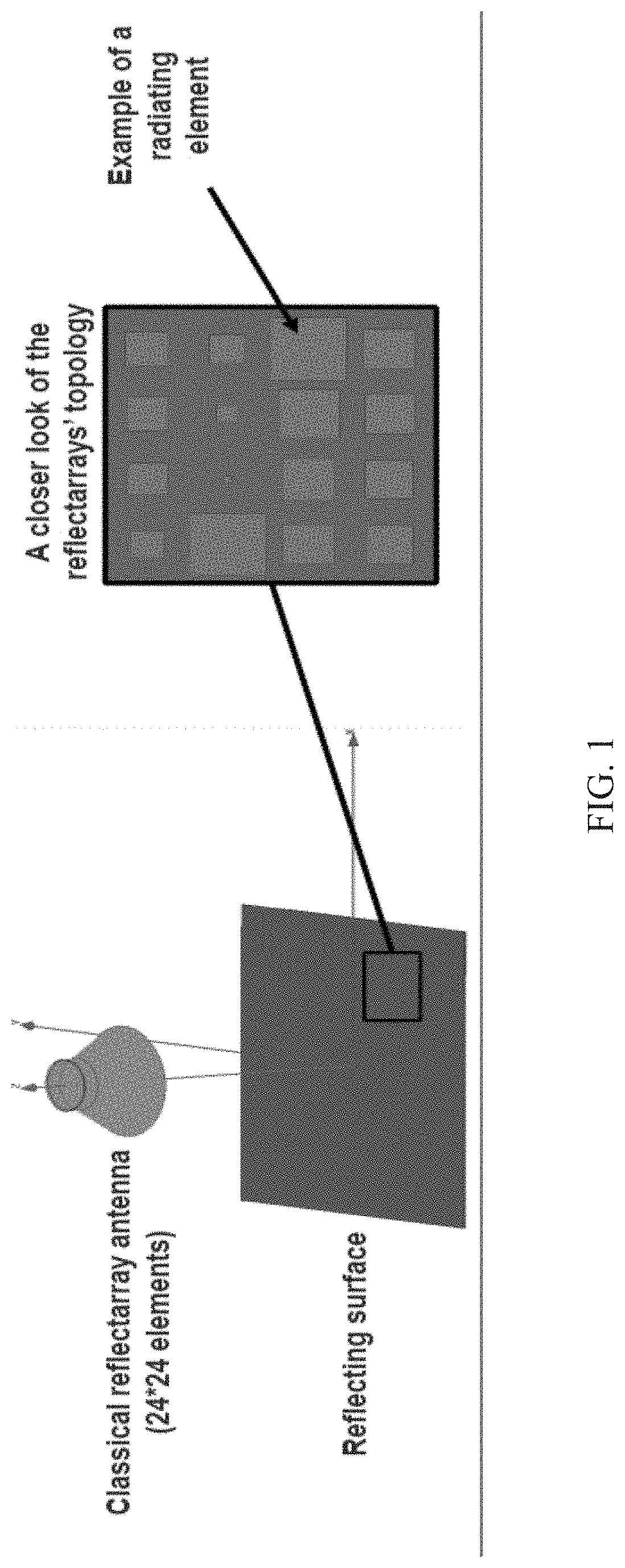
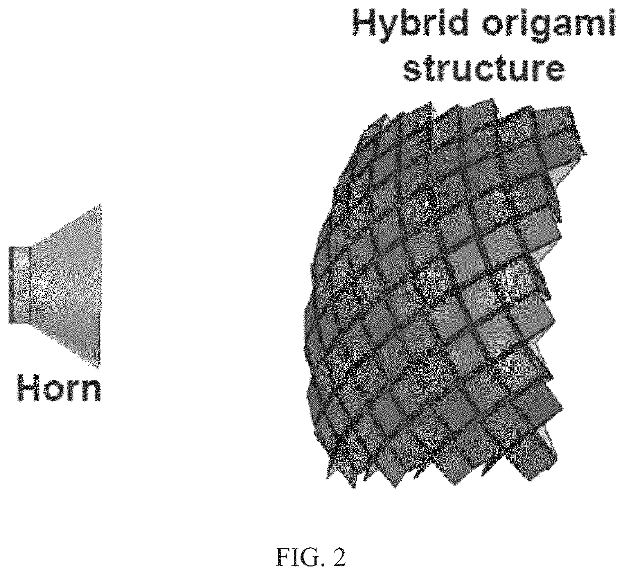
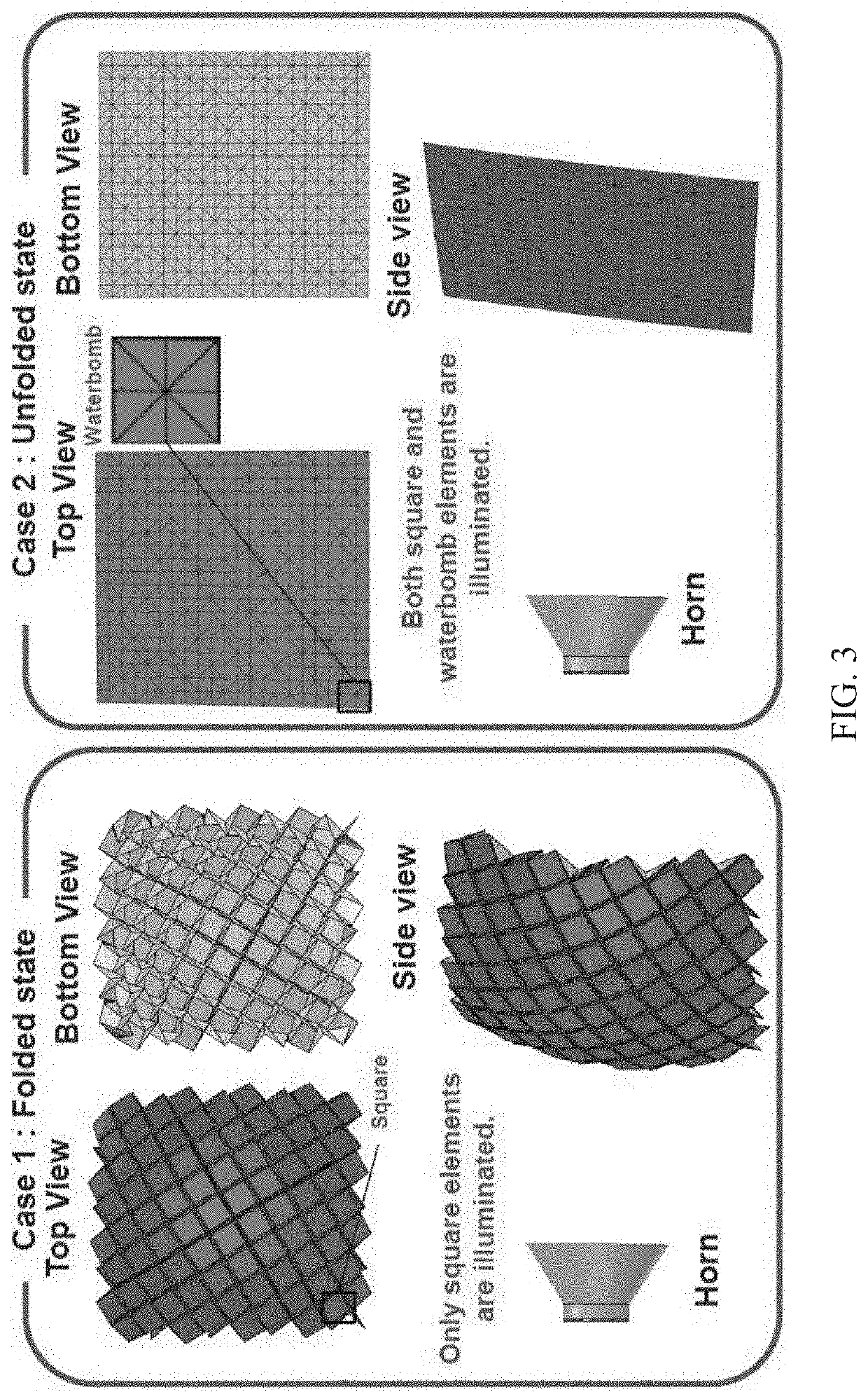
[0018]Embodiments of the subject invention provide novel and advantageous arrays that are deployable and can change their electromagnetic (EM) behavior by changing their shape. The arrays can steer the beam using folding techniques and / or can achieve multiple operation states by folding the structure. The arrays can fold and unfold using any suitable actuation system known in the art (e.g., a motor or robotics). An array can include a foldable substrate (e.g., an origami substrate) with one or more antenna elements (e.g., an antenna element in each unit cell) disposed thereon. The foldable substrate can have predefined folding lines (e.g., folding lines for mountain- and / or valley-style folds) and / or hinges such that the foldable substrate can be folded into at least one particular predetermined shape in each folded state and can lay flat in an unfolded state. In a folded state, a first plurality of unit cells is visible from above the array and can be configured to steer in a parti...


PUM


Abstract

Arrays that are deployable and can change their electromagnetic behavior by changing their shape are provided. The arrays can steer the beam using folding techniques and/or can achieve multiple operation states by folding the structure. An array can include a foldable substrate with antenna elements disposed thereon. In a folded state, a first plurality of unit cells is visible from above the array and can be configured to steer in a particular first direction and/or operate at a particular first frequency. In the unfolded state a second plurality of unit cells, and also possibly the first plurality of unit cells, are visible from above the array and can be configured to steer in a particular second direction and/or operate at a particular second frequency.

Description

GOVERNMENT SUPPORT[0001]This invention was made with government support under Award Number FA9550-18-1-0191 awarded by the Air Force. The government has certain rights in the invention.BACKGROUND[0002]Cubesat missions for low earth orbit have seen explosive growth over the last decade as they offer new opportunities to expand space exploration and provide better telecommunication capabilities due to their short design time and low fabrication cost. Space communication systems need high gain antennas (HGAs) such as reflectarrays and parabolic reflectors. Reflectarrays are the most commonly used concept for CubeSat HGAs because they offer small stowed volume, low mass, and low cost. However, these reflectarrays radiate in only one pre-defined direction while in real applications multiple radiating directions are highly desired.[0003]Typically, to steer the beam in different directions complicated feeding networks are required, such as beamformers. Beamformers can be either passive or ...

Claims


Application Information

Patent Timeline
Patent Type & Authority Patents(United States)
IPC IPC(8): H01Q15/16H01Q3/01H01Q15/14H01Q21/22
CPCH01Q15/161H01Q3/01H01Q15/148H01Q21/22H01Q15/147
Inventor KADDOUR, ABDUL-SATTARZEKIOS, CONSTANTINOS L.GEORGAKOPOULOS, STAVROS
Owner FLORIDA INTERNATIONAL UNIVERSITY
Why Eureka
Try Eureka