Rerouting in connection-oriented communication networks and communication systems

a communication network and communication system technology, applied in data switching networks, frequency-division multiplexes, instruments, etc., can solve problems such as affecting connection recovery and end user disconnections

Inactive Publication Date: 2007-02-20
RPX CLEARINGHOUSE
View PDF6 Cites 229 Cited by
  • Summary
  • Abstract
  • Description
  • Claims
  • Application Information

AI Technical Summary

Problems solved by technology

However, the end user's are impacted by being disconnected.
This will, however, impact connection recovery in large networks where the connection recovery service is made scalable by dividing the network into separate rerouting domains.

Method used


Image

  • Rerouting in connection-oriented communication networks and communication systems
  • Rerouting in connection-oriented communication networks and communication systems
  • Rerouting in connection-oriented communication networks and communication systems

Examples


Embodiment Construction

I. Edge-Based Rerouting (EBR)

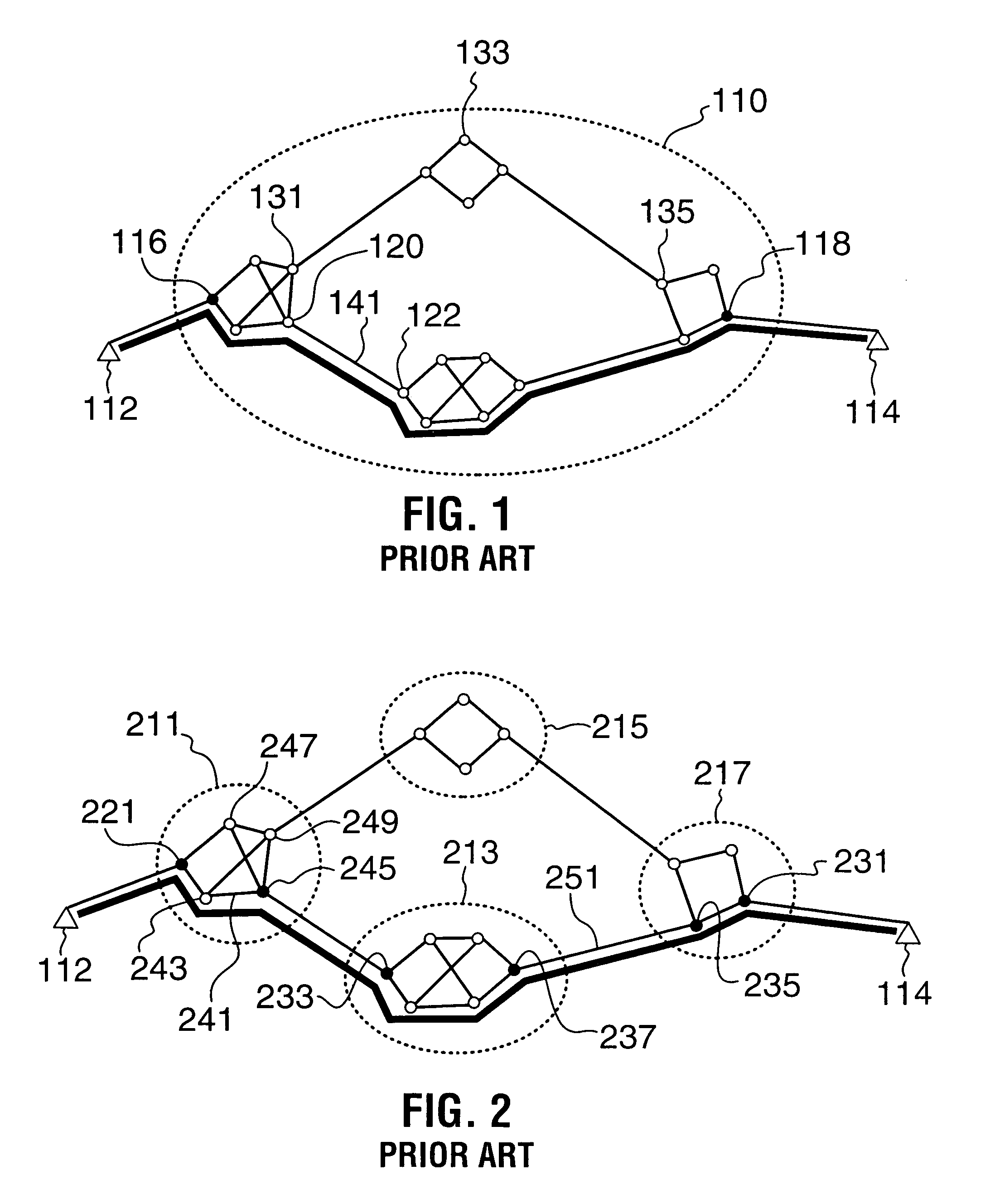
[0025]FIG. 1 illustrates an example of a known Edge-Based Rerouting (EBR) implementation based on a known ATM Forum EBR specification. In FIG. 1, an EBR rerouting domain 110 encompasses the PNNI network including multiple ATM communication nodes. The multiple nodes are defined inside the boundary of the rerouting domain 110, so as that the EBR protocol allows call recovery and path optimization inside the boundary. The nodes are interconnected by respective routing links. For example, each link is basically a communication channel or circuit which defines a topological relationship between two nodes connected thereby. A source customer premise equipment (CPE) 112 originates a call connection with the network at an edge node 116 (“originator”) to another edge node 118 (“terminator”) to establish a call path to a destination CPE 114 through other edge nodes (e.g., nodes 120 and 122).

[0026]Each of the nodes includes a connection admission control (CAC) comp...


PUM


Abstract

A Private Network-Network Interface (PNNI) network including interconnected nodes is defined as a single rerouting domain (“global domain”) and the global domain is further defined by multiple divided domains (“local domains”). Each of the local domains is defined to include multiple nodes that are included in the network. Connection recovery and path optimization in the global domain (the entire PNNI network) are performed in accordance with a global rerouting protocol. The global rerouting protocol is a modification of the standard Domain-Based Rerouting (DBR) protocol, by adding information elements of domain identifier, rerouting for the global domain. The DBR protocol does not support the connection recovery from a link failure between local domains (“inter-domains”) and the global path optimization. The global rerouting method is capable of connection recovery and path optimization outside of any rerouting local domains. The global rerouting provides double fault recovery within the rerouting domain (“intra-domain”) as covered by the DBR and outside of the domains (“inter-domain”) or when the initial fault recovery within the domain has failed. Also, the global rerouting method provides maximum path optimization across all domains and within the rerouting local domain.

Description

TECHNICAL FIELD[0001]The present invention relates generally to rerouting in connection-oriented communication networks and in particular to rerouting for connection recovery and path optimization in connection-oriented networks, for example, Asynchronous Transfer Mode (ATM) and Multi-Protocol Label-Switching (MPLS) networks. The present invention is also applicable to the connection recovery from a failure in Time Division Multiplexed (TDM) and Optical networks.BACKGROUND INFORMATION[0002]Through the efforts of the ATM Forum, a protocol standard that enables the building of multivendor, interoperable ATM switching networks has been developed. The protocol standard relates to ATM connections within the Private Network-Network Interface (PNNI) domain. The protocol allows for the building and maintenance of large ATM networks because it provides hierarchical, dynamic link-state routing instructions and communication pathways. The PNNI routing is based on well-known, link-state routing...

Claims


Application Information

Patent Timeline
Patent Type & Authority Patents(United States)
IPC IPC(8): G01R31/08
CPCH04L45/04H04L45/10H04L45/22H04L45/28H04L43/0811H04Q2213/13141H04Q2213/13204H04Q2213/1329H04Q2213/13292H04Q2213/13348H04Q2213/13389H04Q2213/13145
Inventor CHARTRE, DENISZGIERSKI, JACKNEWELL, DARRENSTEPHENS, RICHARD
Owner RPX CLEARINGHOUSE
Why Eureka
Try Eureka